AD9852/PCBZ Analog Devices Inc, AD9852/PCBZ Datasheet - Page 7
AD9852/PCBZ
Manufacturer Part Number
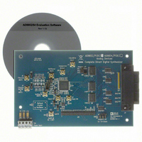
AD9852/PCBZ
Description
300 Mhz C-DDS Synthesizer Eval Board
Manufacturer
Analog Devices Inc
Series
AgileRF™r
Type
Synthesizerr
Datasheet
1.AD9852ASTZ.pdf
(52 pages)
Specifications of AD9852/PCBZ
Lead Free Status / RoHS Status
Lead free / RoHS Compliant
For Use With/related Products
AD9852
Lead Free Status / RoHS Status
Lead free / RoHS Compliant


Parameter
PARALLEL I/O TIMING CHARACTERISTICS
CMOS LOGIC INPUTS
POWER SUPPLY
1
2
3
4
5
6
7
8
9
10
11
12
13
The reference clock inputs are configured to accept a 1 V p-p (typical) dc offset square or sine waves centered at one-half the applied V
An internal 400 mV p-p differential voltage swing equates to 200 mV p-p applied to both REFCLK input pins.
Pipeline delays of each individual block are fixed; however, if the first eight MSBs of a tuning word are all 0s, the delay appears longer. This is due to insufficient phase
accumulation per a system clock period to produce enough LSB amplitude to the D/A converter.
If a feature such as inverse sinc, which has 16 pipeline delays, can be bypassed, the total delay is reduced by that amount.
The I/O UD CLK transfers data from the I/O port buffers to the programming registers. This transfer is measured in system clocks.
A change in duty cycle from 1 MHz to 100 MHz with 1 V p-p sine wave input and 0.5 V threshold.
Represents the comparator’s inherent cycle-to-cycle jitter contribution. The input signal is a 1 V, 40 MHz square wave, and the measurement device is a Wavecrest DTS-2075.
Comparator input originates from analog output section via external 7-pole elliptic low-pass filter. Single-ended input, 0.5 V p-p. Comparator output terminated in 50 Ω.
Avoid overdriving digital inputs. (Refer to equivalent circuits in Figure 3.)
If all device functions are enabled, it is not recommended to simultaneously operate the device at the maximum ambient temperature of 85°C and at the maximum
All functions engaged.
All functions except inverse sinc engaged.
All functions except inverse sinc and digital multipliers engaged.
internal clock frequency. This configuration may result in violating the maximum die junction temperature of 150°C. Refer to the Power Dissipation and Thermal
Considerations section for derating and thermal management information.
t
t
t
t
t
t
t
t
t
t
t
SERIAL I/O TIMING CHARACTERISTICS
t
t
t
t
t
t
t
Logic 1 Voltage
Logic 0 Voltage
Logic 1 Current
Logic 0 Current
Input Capacitance
V
V
V
P
P
P
P
ASU
ADHW
DSU
DHD
WRLOW
WRHIGH
WR
ADV
ADHR
RDLOV
RDHOZ
PRE
SCLK
DSU
SCLKPWH
SCLKPWL
DHLD
DV
S
S
S
DISS
DISS
DISS
DISS
Current
Current
Current
(Data Valid Time)
(Minimum WR Time)
(CS Setup Time)
(Address Setup Time to WR Signal Active)
(Data Setup Time to WR Signal Inactive)
(Address to Data Valid Time)
(Serial Data Setup Time)
(Data Hold Time to WR Signal Inactive)
(Period of Serial Data Clock)
11
12
13
Power-Down Mode
(Address Hold Time to RD Signal Inactive)
(Serial Data Hold Time)
(Address Hold Time to WR Signal Inactive)
(RD Low to Output Valid)
(RD High to Data Three-State)
(WR Signal Minimum Low Time)
(WR Signal Minimum High Time)
(Serial Data Clock Pulse Width Low)
(Serial Data Clock Pulse Width High)
11
12
13
10
9
Temp
Full
Full
Full
Full
Full
Full
Full
Full
Full
Full
Full
Full
Full
25°C
25°C
25°C
25°C
25°C
25°C
25°C
25°C
25°C
Full
Full
Full
Full
Full
25°C
25°C
25°C
Rev. E | Page 7 of 52
Level
IV
IV
I
Test
IV
IV
IV
IV
IV
IV
IV
V
IV
IV
IV
IV
IV
IV
IV
IV
IV
V
I
I
V
I
I
I
I
I
I
Min
8.0
0
3.0
0
2.5
7
10.5
15
5
30
100
30
40
40
0
2.2
AD9852ASVZ
Typ
7.5
1.6
1.8
30
3
815
640
585
2.70
2.12
1.93
1
Max
± 5
± 5
922
725
660
3.20
2.52
2.29
50
15
15
10
0.8
Min
8.0
0
3.0
0
2.5
7
10.5
15
5
30
100
30
40
40
0
2.2
AD9852ASTZ
Typ
7.5
1.6
1.8
30
3
585
465
425
1.93
1.53
1.40
1
DD
or a 3 V TTL-level pulse input.
Max
15
15
10
0.8
± 12
± 12
660
520
475
2.39
1.81
1.65
50
Unit
ns
ns
ns
ns
ns
ns
ns
ns
ns
ns
ns
ns
ns
ns
ns
ns
ns
ns
V
V
μA
μA
pF
mA
mA
mA
W
W
W
mW
AD9852
Related parts for AD9852/PCBZ
Image
Part Number
Description
Manufacturer
Datasheet
Request
R

Part Number:
Description:
BOARD EVAL FOR AD9852
Manufacturer:
Analog Devices Inc
Datasheet:

Part Number:
Description:
±1.7g Dual-Axis IMEMS Accelerometer Evaluation Board
Manufacturer:
Analog Devices Inc
Datasheet:
Part Number:
Description:
Inertial Sensor Evaluation System
Manufacturer:
Analog Devices Inc
Datasheet:
Part Number:
Description:
Manufacturer:
Analog Devices Inc
Datasheet:
Part Number:
Description:
Manufacturer:
Analog Devices Inc
Datasheet:
Part Number:
Description:
Manufacturer:
Analog Devices Inc
Datasheet:
Part Number:
Description:
Manufacturer:
Analog Devices Inc
Datasheet:
Part Number:
Description:
Manufacturer:
Analog Devices Inc
Datasheet:
Part Number:
Description:
Manufacturer:
Analog Devices Inc
Datasheet:
Part Number:
Description:
Manufacturer:
Analog Devices Inc
Datasheet:
Part Number:
Description:
Manufacturer:
Analog Devices Inc
Datasheet:
Part Number:
Description:
Manufacturer:
Analog Devices Inc
Datasheet:
Part Number:
Description:
Manufacturer:
Analog Devices Inc
Datasheet: