AD9852/PCBZ Analog Devices Inc, AD9852/PCBZ Datasheet - Page 19
AD9852/PCBZ
Manufacturer Part Number
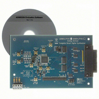
AD9852/PCBZ
Description
300 Mhz C-DDS Synthesizer Eval Board
Manufacturer
Analog Devices Inc
Series
AgileRF™r
Type
Synthesizerr
Datasheet
1.AD9852ASTZ.pdf
(52 pages)
Specifications of AD9852/PCBZ
Lead Free Status / RoHS Status
Lead free / RoHS Compliant
For Use With/related Products
AD9852
Lead Free Status / RoHS Status
Lead free / RoHS Compliant


Table 7. Function Availability vs. Mode of Operation
Function
Phase Adjust 1
Phase Adjust 2
Single-Pin FSK/BPSK or HOLD
Single-Pin Output Shaped Keying
Phase Offset or Modulation
Amplitude Control or Modulation
Inverse Sinc Filter
Frequency Tuning Word 1
Frequency Tuning Word 2
Automatic Frequency Sweep
UNRAMPED FSK (MODE 001)
When this mode is selected, the output frequency of the DDS is
a function of the values loaded into Frequency Tuning Word
Register 1 and Frequency Tuning Word Register 2 and the logic
level of Pin 29 (FSK/BPSK/HOLD). A logic low on Pin 29
chooses F1 (Frequency Tuning Word 1, Parallel Address 4 hex
to Parallel Address 9 hex), and a logic high chooses F2
(Frequency Tuning Word 2, Parallel Register Address A hex to
Parallel Register Address F hex). Changes in frequency are
phase continuous and are internally coincident with the FSK
data pin (Pin 29); however, there is deterministic pipeline delay
between the FSK data signal and the DAC output (see Table 1).
The unramped FSK mode (see Figure 33) is representative
of traditional FSK, radio teletype (RTTY), or teletype (TTY)
transmission of digital data. FSK is a very reliable means of
digital communication; however, it makes inefficient use of
the bandwidth in the RF spectrum. Ramped FSK, shown in
Figure 34, is a method of conserving the bandwidth.
FSK DATA (PIN 29)
I/O UD CLK
MODE
TW1
TW2
FREQUENCY
000 (DEFAULT)
F2
F1
0
0
0
Single-Tone Mode
Figure 33. Unramped (Traditional) FSK Mode
●
●
●
●
●
●
Rev. E | Page 19 of 52
FSK Mode
●
●
●
●
●
●
●
●
001 (FSK NO RAMP)
RAMPED FSK (MODE 010)
In this method of FSK, changes from F1 to F2 are not
instantaneous, but are accomplished in a frequency sweep or
ramped fashion. The ramped notation implies the sweep is
linear. Although linear sweeping, or frequency ramping, is
easily and automatically accomplished, it is only one of many
possibilities. Other frequency transition schemes can be
implemented by changing the ramp rate and ramp step size at
any time during operation.
Frequency ramping, whether linear or nonlinear, necessitates
that many intermediate frequencies between F1 and F2 are
output in addition to the primary F1 and F2 frequencies.
Figure 34 and Figure 35 graphically depict the frequency vs.
time characteristics of a linear ramped FSK signal.
In ramped FSK mode, the delta frequency word (DFW) is
required to be programmed as a positive twos complement
value. Another requirement is that the lowest frequency (F1) be
programmed in the Frequency Tuning Word 1 registers.
F1
F2
Ramped FSK Mode
●
●
●
●
●
●
●
●
●
Chirp Mode
●
●
●
●
●
●
●
●
BPSK Mode
AD9852
●
●
●
●
●
●
●
Related parts for AD9852/PCBZ
Image
Part Number
Description
Manufacturer
Datasheet
Request
R

Part Number:
Description:
BOARD EVAL FOR AD9852
Manufacturer:
Analog Devices Inc
Datasheet:

Part Number:
Description:
±1.7g Dual-Axis IMEMS Accelerometer Evaluation Board
Manufacturer:
Analog Devices Inc
Datasheet:
Part Number:
Description:
Inertial Sensor Evaluation System
Manufacturer:
Analog Devices Inc
Datasheet:
Part Number:
Description:
Manufacturer:
Analog Devices Inc
Datasheet:
Part Number:
Description:
Manufacturer:
Analog Devices Inc
Datasheet:
Part Number:
Description:
Manufacturer:
Analog Devices Inc
Datasheet:
Part Number:
Description:
Manufacturer:
Analog Devices Inc
Datasheet:
Part Number:
Description:
Manufacturer:
Analog Devices Inc
Datasheet:
Part Number:
Description:
Manufacturer:
Analog Devices Inc
Datasheet:
Part Number:
Description:
Manufacturer:
Analog Devices Inc
Datasheet:
Part Number:
Description:
Manufacturer:
Analog Devices Inc
Datasheet:
Part Number:
Description:
Manufacturer:
Analog Devices Inc
Datasheet:
Part Number:
Description:
Manufacturer:
Analog Devices Inc
Datasheet: