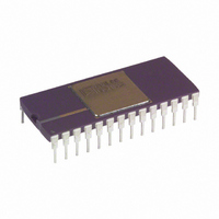
AD678KD Analog Devices Inc, AD678KD Datasheet - Page 9

AD678KD
Manufacturer Part Number
AD678KD
Description
A/D Converter (A-D) IC
Manufacturer
Analog Devices Inc
Datasheet
1.AD678JNZ.pdf
(14 pages)
Specifications of AD678KD
No. Of Bits
12 Bit
Mounting Type
Through Hole
Features
BiMOS, High-Impedance/-Bandwidth, 10V, AC/DC
No. Of Channels
1
Interface Type
Parallel
Package / Case
28-CDIP
Rohs Status
RoHS non-compliant
Number Of Bits
12
Sampling Rate (per Second)
200k
Data Interface
Parallel
Number Of Converters
2
Power Dissipation (max)
745mw
Voltage Supply Source
Analog and Digital, Dual ±
Operating Temperature
0°C ~ 70°C
Lead Free Status / RoHS Status
Available stocks
Company
Part Number
Manufacturer
Quantity
Price
Part Number:
AD678KD
Manufacturer:
ADI/亚德诺
Quantity:
20 000
REV. C
CONVERSION CONTROL
In synchronous mode (SYNC = HIGH), both Chip Select (CS)
and Start Convert (SC) must be brought LOW to start a con-
version. CS should be LOW t
asynchronous mode (SYNC = LOW), a conversion is started by
bringing SC low, regardless of the state of CS.
Before a conversion is started, End-of-Convert (EOC) is HIGH,
and the sample-hold is in track mode. After a conversion is
started, the sample-hold goes into hold mode and EOC goes
LOW, signifying that a conversion is in progress. During the
conversion, the sample-hold will go back into track mode and
start acquiring the next sample. EOC goes HIGH when the con-
version is finished.
In track mode, the sample-hold will settle to ± 0.01% (12 bits)
in 1 µs maximum. The acquisition time does not affect the
throughput rate as the AD678 goes back into track mode more
than 1 µs before the next conversion. In multichannel systems,
the input channel can be switched as soon as EOC goes LOW if
the maximum throughput rate is needed.
Unipolar Coding
(Straight Binary)
V
0 V
5.000 V
9.9976 V
*Code center.
Unipolar
Mode
Bipolar
Mode
NOTES
1 = HIGH voltage level.
0 = LOW voltage level.
X = Don’t care.
U = Logical OR.
IN
*
12-Bit Mode Coding Format (1 LSB = 2.44 mV)
R/L HBE (CS U OE)
X
1
1
0
0
1
1
0
0
OUTPUT ENABLE TRUTH TABLES
INPUTS
(CS U OE)
1
0
Output Code
000 . . . 0
100 . . . 0
111 . . . 1
12-BIT MODE (12/8 = HIGH)
8-BIT MODE (12/8 = LOW)
X
0
1
0
1
0
1
0
1
INPUTS
a = MSB.
1 = LSB.
1
0
0
0
0
0
0
0
0
OUTPUT
DB11–DB0
High Z
Enable 12-Bit Output
SC
before SC is brought LOW. In
Bipolar Coding
(Twos Complement)
V
–5.000 V
–0.002 V
+0.000 V
+2.500 V
+4.9976 V 011 . . . 1
IN
*
0 0 0 0 a b c d
e f g h i j k l
a b c d e f g h
i j k l 0 0 0 0
a a a a a b c d
e f g h i j k 1
a b c d e f g h
i j k l 0 0 0 0
DB11 . . . DB4
OUTPUTS
High Z
Output Code
100 . . . 0
111 . . . 1
000 . . . 0
010 . . . 0
–9–
END-OF-CONVERT
In asynchronous mode, End-of-Convert (EOC) is an open drain
output (requiring a minimum 3 kΩ pull-up resistor) enabled by
End-of-Convert ENable (EOCEN). In synchronous mode,
EOC is a three-state output which is enabled by EOCEN and
CS. See the Conversion Status Truth Table for details. Access
(t
chronous mode where they are a function of the time constant
formed by the 10 pF output capacitance and the pull-up
resistor.
Synchronous
Asynchronous
NOTES
1 = HIGH voltage level.
0 = LOW voltage level.
X = Don’t care.
X
Synchronous 1
Asynchronous 0
NOTES
l = HIGH voltage level.
0 = LOW voltage level.
X = Don’t care.
*EOC requires a pull-up resistor in asynchronous mode.
BA
= HIGH to LOW transition. Must stay low for t = t
Mode
Mode*
Mode
Mode
) and float (t
CONVERSION STATUS TRUTH TABLE
START CONVERSION TRUTH TABLE
SYNC CS EOCEN EOC
1
1
1
0
0
FD
SYNC CS
1
1
1
1
0
0
0
) timing specifications do not apply in asyn-
INPUTS
0
0
1
X
X
X
X
INPUTS
1
0
0
X
X
X
0
0
X
1
0
0
1
SC
X
0
0
1
0
High Z
High Z
High Z
OUTPUT
0
1
High Z
0
STATUS
No Conversion
Start Conversion
Start Conversion
(Not Recommended)
Continuous Conversion
(Not Recommended)
No Conversion
Start Conversion
Continuous Conversion
(Not Recommended)
CP
.
STATUS
Converting
Not Converting
Either
Either
Converting
Not Converting
Either
AD678


