AD678KD Analog Devices Inc, AD678KD Datasheet
AD678KD
Specifications of AD678KD
Available stocks


Related parts for AD678KD


AD678KD Summary of contents
Page 1
FEATURES AC and DC Characterized and Specified (K, B and T Grades) 200k Conversions per Second 1 MHz Full Power Bandwidth 500 kHz Full Linear Bandwidth 72 dB S/N+D ( Grades) Twos Complement Data Format (Bipolar Mode) ...
Page 2
AD678–SPECIFICATIONS ( MIN MAX AC SPECIFICATIONS f = 10.06 kHz unless otherwise noted) lN Parameter SIGNAL-TO-NOISE AND DISTORTION (S/N+D) RATIO –0.5 dB Input (Referred to –0 dB Input) –20 dB Input (Referred to –20 dB Input) –60 dB ...
Page 3
DC SPECIFICATIONS ( MIN Parameter TEMPERATURE RANGE J, K Grades A, B Grades S, T Grades ACCURACY Resolution Integral Nonlinearity (INL) Differential Nonlinearity (DNL) 1 Unipolar Zero Error (@ +25°C) 1 Bipolar Zero Error (@ +25° ...
Page 4
AD678 (All grades, T TIMING SPECIFICATIONS otherwise noted) Parameter SC Delay Conversion Time l Conversion Rate Convert Pulsewidth Aperture Delay Status Delay 2, 3 Access Time 5 Float Delay Output Delay Format Setup OE Delay Read Pulsewidth Conversion Delay EOCEN ...
Page 5
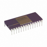
... ESD precautions, refer to Analog Devices’ ESD Prevention Manual. 1 Model Package AD678JN 28-Lead Plastic DIP AD678KN 28-Lead Plastic DIP AD678JD 28-Lead Ceramic DIP AD678KD 28-Lead Ceramic DIP AD678AD 28-Lead Ceramic DIP AD678BD 28-Lead Ceramic DIP AD678AJ 44-Lead Ceramic JLCC AD678BJ 44-Lead Ceramic JLCC ...
Page 6
AD678 28-Lead DIP 44-Lead Symbol Pin No. JLCC Pin No. Type AGND 7 11 AIN 6 10 BIPOFF DGND 14 23 DB11–DB4 26–19 40, 39, 37, 36, DO 35, 34, 33, 31 DB3, DB2 18, ...
Page 7
NYQUIST FREQUENCY An implication of the Nyquist sampling theorem, the “Nyquist Frequency” converter is that input frequency which is one- half the sampling frequency of the converter. SIGNAL-TO-NOISE AND DISTORTION (S/N+D) RATIO S/N+D is the ratio of the ...
Page 8
AD678–Dynamic Performance Figure 4. Harmonic Distortion vs. Input Frequency Figure 5. S/N+D vs. Input Amplitude (f 200 kSPS) SAMPLE Figure 6. S/N+D vs. Input Frequency and Amplitude Figure 7. Nonaveraged 2048 Point FFT at 200 kSPS 49.902 kHz ...
Page 9
CONVERSION CONTROL In synchronous mode (SYNC = HIGH), both Chip Select (CS) and Start Convert (SC) must be brought LOW to start a con- version. CS should be LOW t before SC is brought LOW asynchronous mode (SYNC ...
Page 10
AD678 OUTPUT ENABLE OPERATION The data bits (DB11–DB0) are three-state outputs enabled by Chip Select (CS) and Output Enable (OE). CS should be LOW before OE is brought LOW. Bits DB1 (R/L) and DB0 t OE (HBE) are bidirectional. In ...
Page 11
A single-pass calibration can be done by substituting a bipolar offset trim (error at minus full scale) for the bipolar zero trim (error at midscale), using the same circuit. First, apply a signal 1/2 LSB above minus full scale (–4.9988 ...
Page 12
AD678 AD678 TO TMS320C25 In Figure 14 the AD678 is mapped into the TMS320C25 I/O space. AD678 conversions are initiated by issuing an OUT instruction to Port 8. EOC status and the conversion result are read in with an IN ...
Page 13
REV. C OUTLINE DIMENSIONS Dimensions shown in inches and (mm). 28-Lead Ceramic DIP Package (D-28) 28-Lead Plastic DIP Package (N-28A) –13– AD678 ...
Page 14
AD678 OUTLINE DIMENSIONS Dimensions shown in inches and (mm). 44-Terminal Lead Ceramic (J-44) –14– REV. C ...