EVAL-ADAU1761Z Analog Devices Inc, EVAL-ADAU1761Z Datasheet - Page 63
EVAL-ADAU1761Z
Manufacturer Part Number
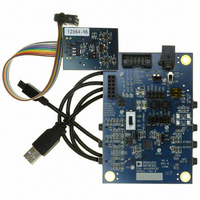
EVAL-ADAU1761Z
Description
Eval Board For ADAU1761
Manufacturer
Analog Devices Inc
Series
SigmaDSP®r
Specifications of EVAL-ADAU1761Z
Main Purpose
Audio, CODEC
Embedded
Yes, DSP
Utilized Ic / Part
ADAU1761
Primary Attributes
Stereo, 24-Bit, 8 ~ 96 kHz Sampling Rate, GUI Tool
Secondary Attributes
I²C and GPIO Interfaces, 2 Differential and 1 Stereo Single-Ended Analog Inputs and Outputs
Silicon Manufacturer
Analog Devices
Core Architecture
SigmaDSP
Silicon Core Number
ADAU1761
Silicon Family Name
SigmaDSP
Application Sub Type
Audio
Lead Free Status / RoHS Status
Lead free / RoHS Compliant
Available stocks
Company
Part Number
Manufacturer
Quantity
Price
Company:

Part Number:
EVAL-ADAU1761Z
Manufacturer:
Analog Devices Inc
Quantity:
135


R14: ALC Control 3, 16,404 (0x4014)
Bit 7
Table 48. ALC Control 3 Register
Bits
[7:6]
5
[4:0]
R15: Serial Port Control 0, 16,405 (0x4015)
Bit 7
Reserved
Table 49. Serial Port Control 0 Register
Bits
6
5
4
3
[2:1]
0
Bit Name
SPSRS
LRMOD
BPOL
LRPOL
CHPF[1:0]
MS
Bit Name
NGTYP[1:0]
NGEN
NGTHR[4:0]
NGTYP[1:0]
Bit 6
Bit 6
SPSRS
Description
Serial port sampling rate source.
0 = converter rate set in Register R17 (default).
1 = DSP rate set in Register R57.
LRCLK mode sets the LRCLK for either a 50% duty cycle or a pulse. The pulse mode should be at least 1 BCLK wide.
0 = 50% duty cycle (default).
1 = pulse mode.
BCLK polarity sets the BCLK edge that triggers a change in audio data. This can be set for the falling or rising
edge of the BCLK.
0 = falling edge (default).
1 = rising edge.
LRCLK polarity sets the LRCLK edge that triggers the beginning of the left channel audio frame. This can be set
for the falling or rising edge of the LRCLK.
0 = falling edge (default).
1 = rising edge.
Channels per frame sets the number of channels per LRCLK frame.
Setting
00
01
10
11
Serial data port bus mode. Both LRCLK and BCLK are master of the serial port when set in master mode and are
serial port slave in slave mode.
0 = slave mode (default).
1 = master mode.
Description
Noise gate type. When the input signal falls below the threshold for 250 ms, the noise gate can hold a constant
PGA gain, mute the ADC output, fade the PGA gain to the minimum gain value, or fade then mute.
Setting
00
01
10
11
Noise gate enable.
0 = disabled (default).
1 = enabled.
Noise gate threshold. When the input signal falls below the threshold for 250 ms, the noise gate is activated.
A 1 LSB increase corresponds to a −1.5 dB change. See Table 93 for a complete list of the threshold settings.
Setting
00000
00001
…
11110
11111
Bit 5
NGEN
Bit 5
LRMOD
Bit 4
Bit 4
BPOL
Noise Gate
Hold PGA constant (default)
Mute ADC output (digital mute)
Fade to PGA minimum value (analog fade)
Fade then mute (analog fade/digital mute)
Threshold
−76.5 dB (default)
−75 dB
…
−31.5 dB
−30 dB
Channels per LRCLK Frame
Stereo (default)
TDM 4
TDM 8
Reserved
Rev. C | Page 63 of 92
Bit 3
Bit 3
LRPOL
Bit 2
Bit 2
NGTHR[4:0]
CHPF[1:0]
Bit 1
Bit 1
ADAU1761
Bit 0
Bit 0
MS
Related parts for EVAL-ADAU1761Z
Image
Part Number
Description
Manufacturer
Datasheet
Request
R


Part Number:
Description:
BOARD EVAL FOR SI270X-A
Manufacturer:
Silicon Laboratories Inc
Datasheet:

Part Number:
Description:
BUCK CONV REF DESIGN KIT IP1201
Manufacturer:
International Rectifier
Datasheet:
Part Number:
Description:
BOARD DEMO SYNC DUAL BUCK CNVTER
Manufacturer:
International Rectifier
Datasheet:
Part Number:
Description:
BOARD DEMO SYNC BUCK CONVETER
Manufacturer:
International Rectifier
Datasheet:

Part Number:
Description:
EVALBOARD/EB Omnidirectional microphone - Analog
Manufacturer:
Analog Devices
Datasheet:
Part Number:
Description:
EVALBOARD/EB Omnidirectional microphone - Analog
Manufacturer:
Analog Devices
Datasheet:


Part Number:
Description:
BOARD EVAL LED DRIVER LT3756
Manufacturer:
Linear Technology
Datasheet:

Part Number:
Description:
BOARD EVAL FOR AD7741/7742
Manufacturer:
Analog Devices Inc
Datasheet:

Part Number:
Description:
±1.7g Dual-Axis IMEMS Accelerometer Evaluation Board
Manufacturer:
Analog Devices Inc
Datasheet:

Part Number:
Description:
IC MULTIPLIER ANALOG 8-SOIC T/R
Manufacturer:
Analog Devices Inc
Datasheet:

Part Number:
Description:
IC ANALOG MULTIPLIER 8-DIP
Manufacturer:
Analog Devices Inc
Datasheet:
Part Number:
Description:
IC ANALOG MULTIPLIER 8-SOIC
Manufacturer:
Analog Devices Inc
Datasheet:
Part Number:
Description:
IC ANALOG MULTIPLIER 8-DIP
Manufacturer:
Analog Devices Inc
Datasheet: