DLP-RF1-Z DLP Design Inc, DLP-RF1-Z Datasheet
DLP-RF1-Z
Specifications of DLP-RF1-Z


Related parts for DLP-RF1-Z


DLP-RF1-Z Summary of contents
Page 1
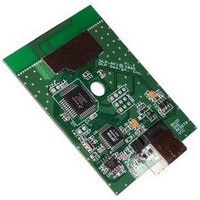
... USB / RF OEM Transceiver Module The DLP-RF1-Z combines a USB interface, Freescale™ MC13193 2.4GHz Direct-Sequence Spread Spectrum RF Transceiver IC and Freescale MC9S08GT60 microcontroller to form an IEEE 802.15.4 compliant, ZigBee™ ready, short-range transceiver module. The MC9S08GT60 microcontroller is preprogrammed with DLP Design’s Serial Interface Packet Processor (SIPP™ firmware) for accessing the transceiver functions via simple serial calls ...
Page 2
... ID (packet destina- tion), the source transceiver ID (packet origin), and a command byte. As shipped from DLP Design, the DLP-RF1 has more than one DLP-RF1 used in a system, then this ID must be changed to a value higher than 2 (the DLP-RF2 has a default ID value of 2). ...
Page 3
... Reserved EEPROM Locations The EEPROM memory is a feature of the preprogrammed SIPP firmware and, as such, is only available when using the DLP-RF1 with its firmware as shipped from DLP Design. The EEPROM memory used by the SIPP firmware consists of a block of 32 bytes that reside within the Flash program memory of the MC9S08GT60 ...
Page 4
... Command Packets. In the case of the DLP-RF1, the host is the user-supplied host PC and associated application program Command Packet is received by the DLP-RF1 via USB with a destination ID that matches the ID stored in the EEPROM of the DLP-RF1, then the MC9S08GT60 will process the packet and reply to the host PC ...
Page 5
... If a packet arrives via the RF transceiver with a non-zero ID that does not match the EEPROM, then the packet is ignored. The only exception to this is if “Return All Packets” Mode is enabled, in which case the DLP-RF1 is monitoring packet traffic, and all unsolicited packets are returned to the serial host. **Under this communication protocol the responsibility of the host application to “Retry” ...
Page 6
... Data Bytes: Current I/O pin state (A6, B6:0), Bit-field with bits set for the port pins that changed state (A6, B6:0) Check-in from DLP-RF2 due to wake from sleep (no data) Measured energy data, 16 Data Bytes: Channel 0 – channel 15 energy levels, ...
Page 7
... DLP-RF1 module. The application program running on the host PC simply has to open what appears RS232C port then build and send a packet to gain access to/control of the DLP- RF1. The VCP drivers intercept the data packets on their way to the RS232C COM port and reroute Rev 1 ...
Page 8
... COM port was opened. The host application must set the baud rate to 9600 baud if using the DLP-RF1-Z. This baud rate can be changed by the host application once connection has been made to the RF1-Z. There is no need for the host application to set the baud rate of the opened COM port to the DLP-RF1. Since the host application is responsible for “ ...
Page 9
... Agency Identification Numbers Compliance with the appropriate regulatory agencies is essential in the deployment of all transceiver devices. DLP Design has obtained modular approval for this RF product such that an OEM need only meet a few basic requirements in order to utilize their end product under this approval. Corresponding ...
Page 10
... Additional Information for OEM Integrators The end user should NOT be provided with any instructions on how to remove or install the DLP-RF1. 5.0 Disclaimer Neither the whole nor any part of the information contained herein nor the product described in this datasheet may be adapted or reproduced in any material or electronic form without the prior written consent of the copyright holder ...