DLP-245PA DLP Design Inc, DLP-245PA Datasheet - Page 8
DLP-245PA
Manufacturer Part Number
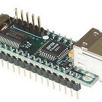
DLP-245PA
Description
Interface Modules & Development Tools USB/Micro Dev Board
Manufacturer
DLP Design Inc
Datasheet
1.DLP-245PA.pdf
(14 pages)
Specifications of DLP-245PA
Interface Type
USB
Data Bus Width
8 bit
Operating Supply Voltage
5 V
Product
Interface Modules
For Use With/related Products
16F872
Lead Free Status / RoHS Status
Lead free / RoHS Compliant


0xA8 – Setup A/D
Parameters:
Returns:
Function:
Example:
0xA9 – A/D Conversion
Parameters:
Returns:
Function:
Example:
0xAA – EEPROM Read
Parameters:
Returns:
Function:
Example:
Port Configuration – Selects analog port configuration. (See command 0xA8 in
the example firmware for options.)
A/D Conversion Clock – Select the source for the A/D conversion clock. (See
command 0xA8 in the example firmware for options.)
Undefined
This function will select the source for the A/D conversion clock. (Refer to the
datasheet for the 16F872 for a detailed explanation of the conversion clock.)
0x3, 0xA8, 0x89, 0x81, 0xA3 – Sets all available A/D inputs on the DLP-245PA to
analog mode (0x89) and selects Fosc/32 for 20MHz operation (0x81).
Analog Port Number – Selects the analog port for the A/D conversion.
2 Bytes: The 10-bit voltage data; LSB first.
This function will set the channel for the A/D conversion, pause 10uS, perform
the A/D conversion, and then return 2 bytes to the host (LSB first). Command
0xA8 must have been previously called to configure the desired analog channel
as an A/D input.
0x2, 0xA9, 0x2, 0xA8 – Selects analog channel 2 (AN2), performs the A/D
conversion, and returns 2 bytes of data.
Address – Selects the zero-based address of the location in the 16F872’s
internal EEPROM for reading.
1 Byte: The byte of data read from the EEPROM.
This function will read the selected location in the 16F872’s internal EEPROM.
0x2, 0xAA, 0x2, 0xAA – Reads EEPROM Address 2, and returns a single byte of
data.
8
Related parts for DLP-245PA
Image
Part Number
Description
Manufacturer
Datasheet
Request
R

Part Number:
Description:
Zigbee / 802.15.4 Modules & Development Tools USE 626-DLP-RF2-Z
Manufacturer:
DLP Design Inc
Datasheet:
Part Number:
Description:
Zigbee / 802.15.4 Modules & Development Tools TTL SERIAL INTERFACE MODULE
Manufacturer:
DLP Design Inc
Datasheet:

Part Number:
Description:
MODULE USB-TO-TTL SRL UART CONV
Manufacturer:
DLP Design Inc
Datasheet:

Part Number:
Description:
Interface Modules & Development Tools FLASH2 TARGET BOARD 18F2321 w/IDE 2k Ltd
Manufacturer:
DLP Design Inc

Part Number:
Description:
Interface Modules & Development Tools FLASH2 TARGET BOARD 16F917 w/IDE 2k Ltd
Manufacturer:
DLP Design Inc

Part Number:
Description:
Interface Modules & Development Tools FLASH2 TARGET BOARD 18F4420 w/IDE 2k Ltd
Manufacturer:
DLP Design Inc
Part Number:
Description:
Zigbee / 802.15.4 Modules & Development Tools TTL SERIAL INTERFACE MODULE
Manufacturer:
DLP Design Inc
Datasheet:

Part Number:
Description:
Interface Modules & Development Tools USB FPGA Module w/ Xilinx XC3S400A
Manufacturer:
DLP Design Inc
Datasheet:

Part Number:
Description:
Interface Modules & Development Tools Dual Ch USB Adapter w/ FTDI FT2232H
Manufacturer:
DLP Design Inc
Datasheet:

Part Number:
Description:
MODULE DATA-ACQUISITION 8-CH
Manufacturer:
DLP Design Inc
Datasheet:

Part Number:
Description:
MODULE USB-MCU FT245RL W/16F877A
Manufacturer:
DLP Design Inc
Datasheet:

Part Number:
Description:
MODULE USB-TO-FPGA TRAINING TOOL
Manufacturer:
DLP Design Inc
Datasheet:

Part Number:
Description:
MODULE USB-MCU FT232R W/18F2410
Manufacturer:
DLP Design Inc
Datasheet:

Part Number:
Description:
MODULE USB-MCU FT245RL W/SX48
Manufacturer:
DLP Design Inc
Datasheet:

Part Number:
Description:
MODULE USB-MCU FT2232D W/16F877A
Manufacturer:
DLP Design Inc
Datasheet: