GP2Y3A003K0F Sharp Microelectronics, GP2Y3A003K0F Datasheet - Page 8
GP2Y3A003K0F
Manufacturer Part Number
GP2Y3A003K0F
Description
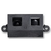
Optical Sensors - Board Mount DMS Wide Angle Sensor 40-300 cm
Manufacturer
Sharp Microelectronics
Datasheet
1.GP2Y3A003K0F.pdf
(10 pages)
Specifications of GP2Y3A003K0F
Maximum Operating Temperature
+ 60 C
Minimum Operating Temperature
- 10 C
Bezel Width
68mm
Detecting Distance
40 To 300cm
External Depth
20mm
External Length / Height
18mm
External Width
53mm
Fixing Hole Diameter
3.2mm
Forward Current If(av)
50mA
Operating Temperature
RoHS Compliant
Svhc
No SVHC (15-Dec-2010)
Rohs Compliant
Yes
Lead Free Status / RoHS Status
Lead free / RoHS Compliant
Lead Free Status / RoHS Status
Lead free / RoHS Compliant
Available stocks
Company
Part Number
Manufacturer
Quantity
Price
Company:

Part Number:
GP2Y3A003K0F
Manufacturer:
EVERLIGHT
Quantity:
40 000


NOTES
• Keep the sensor lens clean. Dust, water, oil, and
• When using a protective cover over the emitter
• Objects in proximity to the sensor may cause reflec-
• Sources of high ambient light (the sun or strong arti-
other contaminants can deteriorate the characteris-
tics of this device. Applications should be designed
to eliminate sources of lens contamination.
and detector, ensure the cover efficiently transmits
light throughout the wavelength range of the LED
(λ = 850 nm ± 70 nm). Both sides of the protective
cover should be highly polished. Use of a protective
cover may decrease the effective distance over
which the sensor operates. Ensure that any cover
does not negatively affect the operation over the
intended application range.
tions that can affect the operation of the sensor.
ficial light) may affect measurement. For best
results, the application should be designed to pre-
vent interference from direct sunlight or artificial light.
Figure 5. Proper Alignment to Surface Being Measured
Figure 6. Proper Alignment to Moving Surfaces
(AVOID IF POSSIBLE)
DIRECTION
OF MOVEMENT
(AVOID IF POSSIBLE)
8
• Using the sensor with a mirror can induce measure-
• If a prominent boundary line exists in the surface being
• When measuring the distance to objects in motion,
• A 10 µF (or larger) bypass capacitor between V
• To clean the sensor, use a dry cloth. Use of any liq-
• Excessive mechanical stress can damage the
ment errors. Often, changing the incident angle on
the mirror can correct this problem.
measured, it should be aligned vertically to avoid mea-
surement error. See Figure 5 for further details.
align the sensor so that the motion is in the horizontal
direction instead of vertical. Figure 6 illustrates the
preferred alignment.
and GND near the sensor is recommended.
uid to clean the device may result in decreased sen-
sitivity or complete failure.
internal sensor or lens.
(PREFERRED)
(PREFERRED)
DIRECTION
OF MOVEMENT
GP2Y3A003K0F
GP2Y3A003K0F-1
GP2Y3A003K0F-2
Data Sheet
CC
Related parts for GP2Y3A003K0F
Image
Part Number
Description
Manufacturer
Datasheet
Request
R

Part Number:
Description:
IC FLASH 32MBIT 110NS 56SSOP
Manufacturer:
Sharp Microelectronics
Datasheet:

Part Number:
Description:
IC FLASH 16MBIT 100NS 56TSOP
Manufacturer:
Sharp Microelectronics
Datasheet:

Part Number:
Description:
IC FLASH 64MBIT 120NS 56TSOP
Manufacturer:
Sharp Microelectronics
Datasheet:

Part Number:
Description:
IC FLASH 16MBIT 90NS 48TSOP
Manufacturer:
Sharp Microelectronics
Datasheet:
Part Number:
Description:
IC SRAM 16KBIT 100NS 24DIP
Manufacturer:
Sharp Microelectronics
Datasheet:
Part Number:
Description:
IC SRAM 16KBIT 100NS 24SOP
Manufacturer:
Sharp Microelectronics
Datasheet:
Part Number:
Description:
IC SRAM 64KBIT 100NS 28DIP
Manufacturer:
Sharp Microelectronics
Datasheet:
Part Number:
Description:
IC SRAM 64KBIT 100NS 28SOP
Manufacturer:
Sharp Microelectronics
Datasheet:
Part Number:
Description:
IC SRAM 64KBIT 100NS 28SOP
Manufacturer:
Sharp Microelectronics
Datasheet:
Part Number:
Description:
IC SRAM 256KBIT 70NS 28DIP
Manufacturer:
Sharp Microelectronics
Datasheet:
Part Number:
Description:
IC FLASH 8MBIT 90NS 48TSOP
Manufacturer:
Sharp Microelectronics
Datasheet:
Part Number:
Description:
IC FLASH 8MBIT 85NS 40TSOP
Manufacturer:
Sharp Microelectronics
Datasheet:
Part Number:
Description:
IC FLASH 8MBIT 85NS 40TSOP
Manufacturer:
Sharp Microelectronics
Datasheet:
Part Number:
Description:
IC FLASH 16MBIT 90NS 48TSOP
Manufacturer:
Sharp Microelectronics
Datasheet:
Part Number:
Description:
IC FLASH 16MBIT 70NS 56TSOP
Manufacturer:
Sharp Microelectronics
Datasheet: