GP2W0110YP0F Sharp Microelectronics, GP2W0110YP0F Datasheet
GP2W0110YP0F
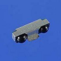
Specifications of GP2W0110YP0F


Related parts for GP2W0110YP0F


GP2W0110YP0F Summary of contents
Page 1
... The GP2W0110YP0F transceiver module has a built-in 0.1-µA-shutdown mode for those applications that are very conscious about current GP2W0110YP0F has a tri-state output, which allows its use in applications where one port connection may be connected to more than one device. The shield is appropriate in applications where Electro-Magnetic Interference (EMI concern ...
Page 2
... ELECTRONIC COMPONENTS 3. Package The dimensional drawing and all packaging information is available on-line at www.sharpsma.com. Select Products/Optoelectronics/IrDA. All available models will be shown and specifications and drawings provided in the available documents. These documents will have the most up-to-date information. 4. Absolute Maximum Ratings Parameter Supply Voltage ...
Page 3
ELECTRONIC COMPONENTS 6. Electrical and Optical Specifications Specifications hold over the Recommended Operating Conditions, unless otherwise noted. All typical values are and V = 2.0 to 3.6V, unless otherwise noted. Refer to specifications for complete details ...
Page 4
... LED Anode 9. Application Electrical Design Hints The only external component needed for the GP2W0110YP0F is a capacitor for filtering any power supply noise. See Section 11 for technical reference data in optical / electrical characteristics. 9-1 Application Circuit and External Passives Following application circuit is recommended. ...
Page 5
... This voltage may be as low as 2.0 Volts to 3.6 Volts, and the V range from 2.0 Volts to 6.0 Volts. An alternative is to connect the V LEDA GP2W0110YP0F to go into previous applications where both of these voltage sources are connected footprint and interface compatible with the previous Sharp GP2W0102YP, GP2W0104YP and GP2W0106YP products. SHARP Electronic Components , March 7, 2002 Rev ...
Page 6
... Normal Operation Mode 9-3 Example of Signal Waveform The following drawing shows the waveform at each point in the block diagram to operate GP2W0110YP0F in a manner conforming to IrDA standards. The waveform example is only applicable as a design and evaluation reference to understand the GP2W0110YP0F hardware implementation and system measurement ...
Page 7
... ELECTRONIC COMPONENTS In process section 1, the PCB and SMD GP2W0110YP0F molded pinout joints are heated to a temperature of 165 the flux in the solder paste. The temperature ramp up rate R1 should be within the range per second. Package temperature must be kept within the temperature range specified in order to avoid localized temperature rise in the resin by the infrared lamp ...
Page 8
ELECTRONIC COMPONENTS 10-2. Designing IR Cosmetic Window Following figure and calculation explain the example and designing hints for cabinet and IR cosmetic window with o +18 viewing angles, in vertical and horizontal axis. All values for the transceiver dimensions are ...
Page 9
... Sharp Microelectronics has prepared an evaluation board for preliminary test of the GP2W0110YP0F transceiver. This board has also been developed to support the GP2W0112YPS transceiver, and that is why there are two resistor positions on the board. In the configuration for GP2W0110YP0F Ohms, and the R1 position is open. (The position for R1 will be loaded when the board is used for GP2W0112YP.) The new low power 20 cm transceivers are so small that soldering directly to the contacts on the device is not an easy or effective connection method ...
Page 10
... SHARP CORPORATION Japan INTERNATIONAL SALES & MARKETING GROUP -IC/ELECTRONIC COMPONENTS 22-22 Nagaike-cho, Abeno-Ku, OSAKA, 545, JAPAN PHONE: (81) 6-621-3129 FAX: (81) 6-624-0163 NORTH AMERICA: SHARP MICROELECTRONICS OF THE AMERICAS 5700 Northwest, Pacific Rim Boulevard #20 Camas, WA 98607 U.S.A. PHONE: (1) 360-834-2500 FAX: (1) 360-834-8903 EUROPE: SHARP ELECTRONICS (EUROPE) GmbH ...