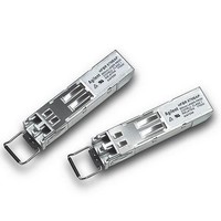
HFBR-57M5AP Avago Technologies US Inc., HFBR-57M5AP Datasheet - Page 10

HFBR-57M5AP
Manufacturer Part Number
HFBR-57M5AP
Description
Fiber Optic Transmitters, Receivers, Transceivers 2/1 GBd FC SFP DMI B ail delatch
Manufacturer
Avago Technologies US Inc.
Datasheet
1.HFBR-57M5AP.pdf
(18 pages)
Specifications of HFBR-57M5AP
Function
Supports high-speed serial links over multimode optical fiber at signaling rates up to 2.125 GBd.
Product
Transceiver
Data Rate
2.125 GBd, 1.0625 GBd, 1.25 GBd
Wavelength
850 nm
Maximum Rise Time
250 ps, 150 ps
Maximum Fall Time
250 ps, 150 ps
Pulse Width Distortion
0.12 ns, 0.123 ns
Operating Supply Voltage
2.97 V to 3.63 V
Maximum Operating Temperature
+ 75 C
Minimum Operating Temperature
- 10 C
Package / Case
SFP-20
Optical Fiber Type
TX/RX
Data Transfer Rate
2125Mbps
Optical Rise Time
0.15/0.25ns
Optical Fall Time
0.15/0.25ns
Jitter
0.12/0.123ns
Operating Temperature Classification
Commercial
Peak Wavelength
860nm
Package Type
SFP
Operating Supply Voltage (min)
2.97V
Operating Supply Voltage (typ)
3.3V
Operating Supply Voltage (max)
3.63V
Operating Temp Range
-10C to 75C
Mounting
Snap Fit To Panel
Pin Count
20
For Use With
Multimode Glass
Lead Free Status / RoHS Status
Lead free / RoHS Compliant
Transceiver Timing Characteristics
TC = -10 °C to +85 °C, V
Notes:
1. Time from rising edge of TX_DISABLE to when the optical output falls below 10% of nominal.
2. Time from falling edge of TX_DISABLE to when the modulated optical output rises above 90% of nominal.
3. From power on or negation of TX_FAULT using TX_DISABLE.
4. Time from fault to TX_FAULT on.
5. Time TX_DISABLE must be held high to reset TX_FAULT.
6. Time from RX_LOS transition to RX_LOS assert per Figure 4.
7. Time from non-RX_LOS transition to RX_LOS de-assert per Figure 4.
8. Contact Avago Technologies for applications requiring higher Serial ID clock rate.
Typical Transceiver Digital Diagnostic Monitor (Real Time Sense) Characteristics
TC = -10 °C to +85 °C, V
Notes:
1. Temperature is measured internal to the transceiver.
2. Voltage is measured internal to the transceiver.
3. Coupled into 50/125 µm multimode fiber. Valid from -10 to 0 dBm avg.
4. Coupled from 50/125 µm multimode fiber. Valid from 49 to 800 µW OMA.
10
Parameter
TX_DISABLE Assert Time
TX_DISABLE Negate Time
Time to initialize, Including reset of TX_FAULT
TX_FAULT Assert Time
TX_DISABLE to Reset
RX_LOS Assert Time
RX_LOS De-assert Time
Serial ID Clock Rate
Parameter
Received Modulated Optical Input Power Accuracy (OMA)
Transmitted Average Optical Output Power Accuracy
Transmitter Laser Dc Bias Current Accuracy
Transceiver Internal Temperature Accuracy
Transceiver Internal Supply Voltage Accuracy
CC
CC
T, V
T, V
CC
CC
R = 3.3 V ± 10%
R = 3.3 V ± 10%
Symbol
t_off
t_on
t_init
t_fault
t_reset
t_loss_on
t_loss_off
f_serial_clock
Symbol
P
P
I
T
V
INT
INT
R
T
INT
Minimum
10
Minimum
± 3.0
± 3.0
± 10
± 3.0
± 0.1
Maximum
10
1
300
100
100
100
100
Units
dB
dB
%
°C
V
Unit
µs
ms
ms
µs
µs
µs
µs
kHz
Notes
4
3
1
2
Notes
1
2
3
4
5
6
7
8


