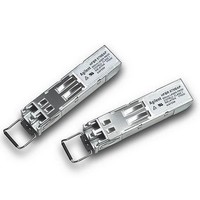
HFBR-57M5AP Avago Technologies US Inc., HFBR-57M5AP Datasheet

HFBR-57M5AP
Specifications of HFBR-57M5AP
Related parts for HFBR-57M5AP
HFBR-57M5AP Summary of contents
Page 1
... Digital Diagnostic Small Form Pluggable Transceiver for Fibre Channel 2.125, 1.0625 GBd and 1.25 GBd Ethernet Data Sheet Description The HFBR-57M5AP is a state of the art transceiver de- signed to provide a cost effective, high performance solution for 2.125 GBd Fibre Channel, 1.0625 GBd Fibre Channel and 1.25 GBd Ethernet applications. ...
Page 2
... Digital Diagnostic Interface and Serial Identification The 2-wire serial protocol is based on the ATMEL AT- 24C01A series EEPROM protocol and signaling detail. The HFBR-57M5AP contains conventional SFP memory per SFF-8074i as well as additional memory (address 0xA2) for new digital diagnostic information. The new diagnostic information provides the oppor- tunity for Predictive Failure Identification, Compliance Prediction, Fault Isolation and Component Monitoring ...
Page 3
... Figure 2 illustrates the recommended interface circuit. Application Support An Evaluation Kit and Reference Designs are available to assist in evaluation of the HFBR-57M5AP. Please contact your local Field Sales representative for availability and ordering details. 1 µH 3 µ ...
Page 4
... Japan. The metal housing and shielded design of the HFBR-57M5AP provides excellent EMI performance. Eye Safety The HFBR-57M5AP transceivers provide Class 1 eye safety by design. Avago Technologies has tested the transceiver design for regulatory compliance, under normal operating conditions and under a single fault condition ...
Page 5
Pin Out Table Pin Name Function/Description Transmitter Ground EE 2 TX_FAULT Transmitter Fault Indication - High indicates a fault condition 3 TX_DISABLE Transmitter Disable - Module opti cal output disables on high or open 4 MOD-DEF2 Module ...
Page 6
Absolute Maximum Ratings Parameter Case Operating Temperature Ambient Operating Temperature Relative Humidity Module Supply Voltage Control Input Voltage Notes: 1. Absolute Maximum Ratings are those values beyond which damage to the device may occur if these limits are exceeded for ...
Page 7
Transceiver Electrical Characteristics TC = -10 °C to +85 ° 3.3 V ± 10 Parameter Data Input: Transmitter Differential Input Voltage (TD±) Data Output: Receiver Differential Output Voltage (RD±) Contributed Deterministic Jitter (Receiver) ...
Page 8
Transmitter Optical Characteristics TC = -10 °C to +85 ° 3.3 V ± 10 Parameter Modulated Optical Output Power (OMA, pk-pk) 2.125 Gb/s Modulated Optical Output Power (OMA, pk-pk) 1.0625 Gb/s Average Optical ...
Page 9
Receiver Optical Characteristics TC = -10 °C to +85 ° 3.3 V ± 10 Parameter Input Optical Power Input Optical Modulation Amplitude (OMA, Pk-Pk) 2.125 Gb/s Input Optical Modulation Amplitude (OMA, Pk-Pk) 1.0625 ...
Page 10
Transceiver Timing Characteristics TC = -10 °C to +85 ° 3.3 V ± 10 Parameter TX_DISABLE Assert Time TX_DISABLE Negate Time Time to initialize, Including reset of TX_FAULT TX_FAULT Assert Time TX_DISABLE to ...
Page 11
Address A0 as per MSA 0 Serial ID defined by SPF MSA (96 Bytes) 95 Vendor Specific (32 Bytes) 127 Reserved in SFP MSA (128 Bytes) 255 Figure 4. Memory Map 11 Address A2 as per MSA 0 Alarm and ...
Page 12
V > 2. Tx_FAULT Tx_DISABLE TRANSMITTED SIGNAL t_init t-init: TX DISABLE NEGATED V > 2. Tx_FAULT Tx_DISABLE TRANSMITTED SIGNAL t_init INSERTION t-init: TX DISABLE NEGATED, MODULE HOT PLUGGED OCCURANCE OF FAULT Tx_FAULT Tx_DISABLE TRANSMITTED SIGNAL t_fault ...
Page 13
... Addresses 68-83 specify the HFBR-57M5AP ASCII serial number and will vary on a per unit basis. 2. Addresses 84-91 specify the HFBR-57M5AP ASCII date code and will vary on a per date code basis. 3. Addresses 63 and 95 are check sums. Address 63 is the check sum for bytes 0–62 and address 95 is the check sum for bytes 64–94. ...
Page 14
Table 3. Alarms and Warning Values – Enhanced Feature Set Memory (Address A2h) High Warning Real-Time Hex Real Value Monitor RX OMA 2AF8 1 0F8D -4 dBm Ibias 109A 8.5 mA Temp 5500 +85 °C V 8DCC 3.63 ...
Page 15
... TX RX AREA FOR PROCESS PLUG DIMENSIONS ARE IN MILLIMETERS (INCHES) Figure 6a. Drawing of SFP Transceiver 15 Avago Technologies HFBR-57M5AP 850 nm LASER PROD 21CFR(J) CLASS 1 COUNTRY OF ORIGIN YYWW XXXXXX 13.8±0.1 [0.541±0.004] 2.60 [0.10] 55.2±0.2 [2.17±0.01] FRONT EDGE OF SFP TRANSCEIVER CAGE 6 ...
Page 16
X Y 16.25 MIN. PITCH B PCB EDGE 5.68 8.58 11.08 16.25 14.25 REF . 2.0 11x 3 3.2 PIN 1 10.93 9.6 0.8 TYP . 1.55 ± 0.05 ∅ 0 DET ...
Page 17
PCB [1.64±.02] 15MAX .59 CAGE ASSEMBLY 12.4REF .49 9.8MAX .39 Figure 6c. 1.7±0.9 [.07±.04] AREA BEZEL FOR PROCESS PLUG Tcase REFERENCE POINT 10REF 1.15REF .39 .05 TO PCB BELOW PCB 0.4±0.1 [.02±0.004] BELOW PCB DIMENSIONS ARE IN ...
Page 18
... Caution The HFBR-57M5AP contains no user serviceable parts. Tampering with or modifying the performance of the HFBR-57M5AP will result in voided product war- ranty. It may also result in improper operation of the HFBR-57M5AP circuitry, and possible overstress of the laser source. Device degradation or product failure may result. Operating above the recommended absolute maximum conditions may be considered an act of mod- ifying or manufacturing a laser product ...


