B6TS-04LT Omron, B6TS-04LT Datasheet - Page 7
B6TS-04LT
Manufacturer Part Number
B6TS-04LT
Description
Capacitance Touch Sensors Sensing IC
Manufacturer
Omron
Series
-r
Type
Capacitiver
Specifications of B6TS-04LT
Sensitivity
-
Response Time
-
Interface
SPI
Channel Inputs
4 Key
Voltage - Supply
3 V ~ 5 V
Actuator Type
-
Package / Case
20-LSSOP (0.173", 4.40mm Width)
Lead Free Status / RoHS Status
Lead free / RoHS Compliant


1.
2.
1
2
3
4
5
6
7,16
8
9
10,
12,
14,
17
11,
13,
15,
18
2.1
2.2
Pin
No.
Overview
This chip is a sensor IC to detect micro capacitances and can be used in touch sensors.
Internally, the chip employs the CMOS process and is contained in a 20-pin SSOP plastic package.
The IC has 4 independent measurement pins, each of which can measure capacitance independently.
On/off output or serial communication output can be selected as the output form.
The IC is provided with an EEPROM that can store operation mode and other parameters.
Pin connections
───
OUT2
SCK
───
OUT3
SD
───
RESET
TEST1
VSS
MEAS
VDD
TEST2
───
SETUP
CH3B
CH2B
CH1B
CH0B
CH3A
CH2A
CH1A
CH0A
Pin arrangement diagram
Pin functions
Desig-
nation
Note 1: Pins TEST1, and TEST2 are used for testing during manufacture of the IC.
When using these pins, connect them to VDD through a pull-up resistor.
I/O
I/O
I
I
I
I
I
I
I
I/O
I/O
Output
Input/
Ground
Supply input (3.0 - 5.5V)
Output pin for measured result
[On/off output mode] channel 2 output (active low)
[Serial communication mode] serial communication clock input
Output pin for measured result
[On/off output mode] channel 3 output (active low)
[Serial communication mode] serial communication data (duplex)
Reset signal input. Inputting low to this pin resets the chip.
Connect this pin to VDD through a pull-up resistor of about 5kΩ. When VDD starts
up, the power-on reset function operates and the chip is initialized.
When the power-on reset function is used, no other reset signal is needed when power
is turned on.
(Connect to VDD through a pull-down resistor.)
Initiation of measurement. Capacitance measurement is initiated by inputting high to
this pin. While low is input to this pin, the chip is held in standby status.
(Connect to VDD through a pull-down resistor.)
Setup mode. Low input to this pin moves the chip into setup mode.
Measurement pins B (channel 3 - 0)
Connect these pins to the touch electrode through resistors.
Measurement pins A (channel 3 - 0)
Connect these pins to the touch electrode through resistors.
Function
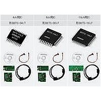
Related parts for B6TS-04LT
Image
Part Number
Description
Manufacturer
Datasheet
Request
R

Part Number:
Description:
SENSOR, CAP TOUCH, 4 CH, SMD, SOP20
Manufacturer:
Omron
Datasheet:

Part Number:
Description:
Capacitance Touch Sensors Touch Switch
Manufacturer:
Omron
Datasheet:

Part Number:
Description:
Capacitance Touch Sensors Sensing IC
Manufacturer:
Omron
Datasheet:

Part Number:
Description:
G6S-2GLow Signal Relay
Manufacturer:
Omron Corporation
Datasheet:
Part Number:
Description:
Compact, Low-cost, SSR Switching 5 to 20 A
Manufacturer:
Omron Corporation
Datasheet:
Part Number:
Description:
Manufacturer:
Omron Corporation
Datasheet:
Part Number:
Description:
Manufacturer:
Omron Corporation
Datasheet:
Part Number:
Description:
Manufacturer:
Omron Corporation
Datasheet:
Part Number:
Description:
Manufacturer:
Omron Corporation
Datasheet:
Part Number:
Description:
Manufacturer:
Omron Corporation
Datasheet: