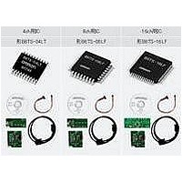
B6TS-04LT Omron, B6TS-04LT Datasheet - Page 18

B6TS-04LT
Manufacturer Part Number
B6TS-04LT
Description
Capacitance Touch Sensors Sensing IC
Manufacturer
Omron
Series
-r
Type
Capacitiver
Specifications of B6TS-04LT
Sensitivity
-
Response Time
-
Interface
SPI
Channel Inputs
4 Key
Voltage - Supply
3 V ~ 5 V
Actuator Type
-
Package / Case
20-LSSOP (0.173", 4.40mm Width)
Lead Free Status / RoHS Status
Lead free / RoHS Compliant
7.2
7.3
To perform teaching, this chip must be brought into setup mode and some parameters must be set.
The parameters (commands) associated with teaching are as follows:
7.2.1 Teaching measurement count (Refer to “6.2.8 TCAL: Teaching measurement count”)
7.2.2 Quantity of variation judged as on (Refer to “6.2.15 THRx: Quantity of variation judged as on”.)
7.2.3 Hysteresis (Refer to “6.2.16 HYSx: Hysteresis of each channel”.)
7.2.4 On-judgment ratio (Refer to “6.2.17 RTHRx: On-judgment ratio for each channel”) &
Preparation for teaching
Performing teaching
There are two ways to enter teaching mode:
When entering teaching mode by method (1), set the /SETUP pin to high or the MEAS pin to low before
teaching finishes. If /SETUP pin = high and the MEAS pin = low, teaching will commence again.
When entering teaching mode, the CHG pin changes to high, indicating entry to teaching mode.
Just after teaching has started, the chip calibrates the reference value (REFx) (the measured value with no-touch).
The measurement is performed eight times for each electrode, and the average of the eight measured values is
taken as REFx. After the calibration finishes, the CHG pin output changes to low. Do not touch the touch
electrode until the CHG pin changes to low.
During teaching, measurement is executed x number of times where x is the value of this parameter × 32.
(Hereafter, this is referred to as the teaching measurement count)
It takes 30–100 msec for one teaching measurement (depending on external circuit constants), and if this
parameter is set to 10, the touches must be executed within 10-30 seconds.
Unless each electrode is touched three times within the number of teaching measurements after starting
teaching, the teaching is regarded as faulty, and none of the parameters are updated.
However, when this parameter is set to “0”, only the reference value (REFx) is updated. In this case, no
touching is required, and the teaching is not regarded as faulty even if no touches are executed.
This parameter contains the quantity of variation of the measured value that will allow judgment of a touch
(approximate value).
To distinguish between variation of the measured value caused by a noise or the like and variation caused by
touching during teaching, this parameter must be set to an approximate value.
If variation of half of this set value occurs during teaching, the electrode is judged touched. Therefore, an
approximate value for variation likely to have been caused by touch may be entered.
This parameter sets the hysteresis value in teaching (approximate value).
Hysteresis ratio (Refer to “6.2.17 RHYSx: Hysteresis ratio for each channel”)
These parameters set the ratios of the quantity of variation judged as on (THRx) and hysteresis (HYSx) to the
variation of the measured value caused by touch.
During teaching, each electrode must be touched three times or more. Then, the minimum value of the
quantity of variation caused by touch is calculated for each electrode of the chip. (Minimum value of quantity
of variation)
The new quantity of variation judged as on and the new hysteresis are calculated using the minimum value of
quantity of variation ∆A as:
Measured value
(1) /SETUP pin = low, and MEAS pin = high
(2) Write “0” into bit15 (TS) using the MODE command in setup mode.
Quantity of variation judged as on (THRx) = ∆A×(On-judgment ratio (RTHRx)+1)/16
Hysteresis (HYSx) = ∆A×(Hysteresis ratio (RHYSx))/16
Touch on electrode
THRx =
HYSx =
Time
∆
∆
A×(On-judgment ratio (RTHRx)+1)/16
A×(Hysteresis ratio (RHYSx))/16


