210304 WALTHER, 210304 Datasheet - Page 7
210304
Manufacturer Part Number
210304
Description
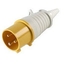
CONNECTOR, POWER ENTRY, PLUG, 16A
Manufacturer
WALTHER
Datasheet
1.210304.pdf
(68 pages)
Specifications of 210304
Gender
Plug
Voltage Rating
110VAC
Current Rating
16A
Connector Mounting
Cable
Connector Type
Standard Power Entry
Lead Free Status / RoHS Status
Lead free / RoHS Compliant


External Cable Gland with “Onion Ring”
Neoprene Bushing
The compression type cable gland serves as a secondary
method of eliminating strain on the terminals and conduc-
tors while assuring watertight performance. Accommodates
various cable sizes. Reliability! Ease of Use!
Retaining Device
Walther pin & sleeve devices are provided with a mechanical arrangement which holds a plug or connector in
position when it is in proper engagement, and prevents its unintentional withdraw.
Electro Zinc Plated Steel Screws
Corrosion resistant. Captive no loose parts to
handle or misplace. Durability! Ease of Use!
High Impact Thermoplastic Housing
The nonmetalic device, while abuse and corrosion resistant, is
also nonconductive, which enhances the safety of the product.
The insulated housing is made from a high impact, nylon
material and is UV stabilized. Safety! Durability
Retaining Device
Holds the plug in position when it is in proper
engagement with a connector or socket-outlet
and prevents its unintentional withdraw
IEC 309 PIN AND SLEEVE DEVICES
IEC 309 PIN AND SLEEVE DEVICES
Terminal Identification
Ground, neutral and phase terminals are clearly
identified for easy recognition and ease of wiring.
Locking Ring and Gasket
Protects against intrusion of dirt, dust and
moisture when the male and female devices
are connected. Reliability!
Double Terminal Screws
Maximum clamping pressure without damag-
ing strands. Double terminal screws create a
large area of safe and secure contact between
conductor and terminal. Screws are captive,
easily accessible and supplied in the open
position. Reliability! Safety!
Split Contact Sleeve with Nickel
Plated Steel Springs
Provides optimum insertion/withdraw force and
constant contact pressure Reliability!
Staggered Contacts
Oversized ground contact is farthest forward,
assuring first make and last break. Neutral is
next to prevent the possibility of an “open neu-
tral” condition. Phase contact is farthest mak-
ing it last to make, first to break. Safety!
Internal Strain Relief with
“Swing-Away” Feature
Designed to firmly grip not only the outer cable jacket
but also the internal conductors. Eliminates strain on the
terminals while providing high pull-out values. “Swing-
Away” feature provides easy access to terminal screws.
Reliability! Ease of Use!
Color Coded
Avoid mismatching. Prevents confusion
with regards to voltage ratings. Safety!
Ease of Use!
Solid Brass Pins
Low contact resistance and high conductivity.
Long lasting, reliable electrical contact. Reliability!
Spring Loaded Gasketed Covers
Protects against accidental encounter with live
contacts. Also, protects against intrusion of dirt,
dust and moisture. A bayonet coupling device is
used to provide optimum stability an simplify
installation. Reliability! Safety!
Chamfered Terminals
Funnel Entry. Guides and captures all wire
strands. Ease of Use! Reliability!
Shrouded Pins
Pins are recessed in the nylon housing and
protected from deforming due to physical
abuse. Eliminates the potential hazard of
touching the live contacts while the plug is
partially engaged. Safety! Reliability!
Recessed Contacts
Contact sleeves are recessed in the narrow
contact tubes thus, providing a “finger proof”
device and protecting against any accidental
encounter with live contacts. Safety!
5
5
Related parts for 210304
Image
Part Number
Description
Manufacturer
Datasheet
Request
R

Part Number:
Description:
CONNECTOR, SCHUKO, SOCKET, 16A
Manufacturer:
WALTHER
Datasheet:

Part Number:
Description:
CONNECTOR, POWER ENTRY, PLUG, 16A
Manufacturer:
WALTHER
Datasheet:

Part Number:
Description:
PLUG, FREE, 230V, 16A, 2P+E WAY
Manufacturer:
WALTHER
Datasheet:

Part Number:
Description:
CONNECTOR, POWER ENTRY, PLUG, 32A
Manufacturer:
WALTHER
Datasheet:

Part Number:
Description:
SOCKET, FREE, 230V, 63A, 2P+E WAY
Manufacturer:
WALTHER
Datasheet:

