210304 WALTHER, 210304 Datasheet - Page 42
210304
Manufacturer Part Number
210304
Description
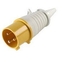
CONNECTOR, POWER ENTRY, PLUG, 16A
Manufacturer
WALTHER
Datasheet
1.210304.pdf
(68 pages)
Specifications of 210304
Gender
Plug
Voltage Rating
110VAC
Current Rating
16A
Connector Mounting
Cable
Connector Type
Standard Power Entry
Lead Free Status / RoHS Status
Lead free / RoHS Compliant


CEEtyp plugs and connectors, with insulation displacement technology, are designed to increase productivity
and lower the installed cost of wire termination. Utilization of the quick connection system for all wiring jobs,
large and small, will speed and improve wire terminations while saving you money. Time and labor savings
can be up to 60% when compared to other connection systems.
No wire stripping – the installation is fast and easy. The usual stripping procedure is not required. Simply
cut the wires to length, fold over and position the conductors in the piercing pockets, and the connection is
complete.
The Walther quick connection system provides an optimum electrical bond between the conductor and the
piercing metal. Once the threaded grip ring is fastened onto the strain relief, the proper amount of force has
been applied providing a uniform and controlled connection.
The insulation displacement connections are designed for wire sizes 18 – 14 AWG (1 – 2.5 mm
suitable for use under extreme conditions such as heavy vibration.
Consult customer service for other amperage and voltage ratings and configurations.
ORDERING INFORMATION
Amps
16
40
Contact Carrier
40
3P + N + G
No. of
Wires
SCREW-LESS PLUGS AND CONNECTORS...
Tapered Cable Sleeve
Voltage AC
Back Shell
400
Locking Tab
SCREW-LESS PLUGS AND CONNECTORS
SCREW-LESS PLUGS AND CONNECTORS
...BROUGHT TO YOU BY WALTHER ELECTRIC
of Ground
Position
Contact
Clock
6
Male Plug
210SL
Counter thread to the grip ring
Threaded Grip Ring
Strain Relief
Positioning Key
Piercing Pocket
Chamber with insulation
displacement contact
Female Connector
310SL
2
) and are
Trim cable cleanly – do not remove cable
jacket at this time.
Cut the tapered cable sleeve to fit snug around
the cable diameter. Be careful not to cut more
than necessary. Remove the backshell by
depressing the locking tab that secures the
contact carrier to the backshell with a small
screwdriver. Slide the backshell and the
threaded grip ring up the cable. Strip the
outer cable jacket about 2 inches (50mm).
Slide the cable through the strain relief (do not
strip the insulation on the individual conduc-
tors), fold over and position the conductors in
the piercing pockets that are marked L1, L2,
L3, N, and Ground. Trim excess conductors to
fit flush.
Align the positioning key on the strain relief
with the keyway on the contact carrier and set
the strain relief into the back of the contact
carrier.
Screw the threaded grip ring onto the strain
relief. Firm tightening by had is sufficient.
This procedure presses the conductors between
the piercing metal providing an optimum
electrical bond while firmly gripping the outer
jacket of the cable.
Slide the backshell down the cable and secure
it to the contact carrier by turning the back-
shell and snapping the locking tab in place.
Related parts for 210304
Image
Part Number
Description
Manufacturer
Datasheet
Request
R

Part Number:
Description:
CONNECTOR, SCHUKO, SOCKET, 16A
Manufacturer:
WALTHER
Datasheet:

Part Number:
Description:
CONNECTOR, POWER ENTRY, PLUG, 16A
Manufacturer:
WALTHER
Datasheet:

Part Number:
Description:
PLUG, FREE, 230V, 16A, 2P+E WAY
Manufacturer:
WALTHER
Datasheet:

Part Number:
Description:
CONNECTOR, POWER ENTRY, PLUG, 32A
Manufacturer:
WALTHER
Datasheet:

Part Number:
Description:
SOCKET, FREE, 230V, 63A, 2P+E WAY
Manufacturer:
WALTHER
Datasheet:

