210304 WALTHER, 210304 Datasheet - Page 4
210304
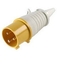
Manufacturer Part Number
210304
Description
CONNECTOR, POWER ENTRY, PLUG, 16A
Manufacturer
WALTHER
Datasheet
1.210304.pdf
(68 pages)
Specifications of 210304
Gender
Plug
Voltage Rating
110VAC
Current Rating
16A
Connector Mounting
Cable
Connector Type
Standard Power Entry
Lead Free Status / RoHS Status
Lead free / RoHS Compliant


WORLDWIDE INTERCHANGEABILITY
Walther’s pin & sleeve devices are built to IEC 309-1 and 309-2
specifications and are interchangeable with other manufacturers
who conform to these IEC standards and color coding system...
anywhere in the world. Manufacturers that do not comply
with these standards have their own proprietary configurations
and are not plug compatible with other pin & sleeve products.
Once you have selected a proprietary configuration you are
locked in to a single source. Specifying IEC 309-1 & 309-2
devices provides convenience and flexibility that users have
come to accept almost without thinking.
SAFETY
IEC 309-2 configurations for plugs (or inlets) and receptacles
(or connectors) are single-rated which assures proper mating
of devices with the same voltage and amperage. It is virtually
impossible to couple a plug and receptacle of different voltage
and /or amperage ratings.
The size of the device is determined by the amperage rating.
Plugs and receptacles of different amperage ratings are not
compatible because of the size variance.
3ØY120/
208V
2
2
3Ø250V
WORLDWIDE INTERCHANGEABILITY, SAFETY AND RELIABILITY...
WORLDWIDE INTERCHANGEABILITY, SAFETY AND RELIABILITY...
3ØY277/480V
Voltage AC (Except where noted)
3Ø/480V
North American Rating
480V
9
10
8
11
7
125/250V
Hour
250V
12
Walther CEEtyp Clockface Positions in Accordance with IEC 309-2 and UL 1686
6
5
1
277V
4
2
3
3Ø600V
3ØY347/600
125V
250VDC
440 (60 Hz)
380 (50Hz)
50 to 600V
400Hz
5 Wire
4 Wire
3 Wire
Many proprietary pin & sleeve configurations, that do not
conform to the IEC standards, are designed to accommodate
multiple voltage systems. A plug wired to a piece of equipment
designed to operate at one voltage system could unintentionally
be plugged into a receptacle wired with an unlike voltage.
Mismatching voltages could cause damage to the equipment or
even personal injury and is not considered safe electrical practice.
The voltage, of single rated Pin & Sleeve devices of the IEC
309-2 type, is determined by the location of the oversized
female ground contact relative to the key-way located at the
bottom of the housing. A clock face is used to represent the
location of the ground sleeve for a specific voltage system.
For example, a 480 VAC receptacle or connector will have the
oversized ground sleeve located in the 7 o'clock position. The
corresponding grounding pin location on the plug or inlet is a
mirror image of the female device. Devices of mismatched volt-
age systems simply cannot be mated. Each device is clearly
marked with the voltage system for which it is intended to be
used. The diagram below shows the keying position and the
color coding that is associated with each voltage system.
120/208 to
144/250V
200 to 250V
100 to 300 Hz
Over 50V
to 288/500V
250/440V to
380 to 415V
277/480
265/460V
Voltage AC (Except where noted)
(60 Hz)
Over 250VDC
440 to 460V
480 to 500V
(60 Hz)
480 to
International Rating
500V
9
10
8
11
7
380 to 415V
to 240/415V
200 to 250V
transformer
transformer
Hour
200/346
isolating
isolating
from an
from an
supply
supply
12
6
5
1
277V
2
4
600 to 690V
3
300 to 500 Hz
100 to
Over 50V
130V
347/600 to
250VDC
400/690V
50 to
300 to 500 Hz
100 to
Over 50V
130V
440 (60 Hz)
380 (50Hz)
300 to 500 Hz
57/100 to
75/130V
Over 50V
220/380
250/440
(60 Hz)*
(50 Hz)
5 Wire
4 Wire
3 Wire
Related parts for 210304
Image
Part Number
Description
Manufacturer
Datasheet
Request
R

Part Number:
Description:
CONNECTOR, SCHUKO, SOCKET, 16A
Manufacturer:
WALTHER
Datasheet:

Part Number:
Description:
CONNECTOR, POWER ENTRY, PLUG, 16A
Manufacturer:
WALTHER
Datasheet:

Part Number:
Description:
PLUG, FREE, 230V, 16A, 2P+E WAY
Manufacturer:
WALTHER
Datasheet:

Part Number:
Description:
CONNECTOR, POWER ENTRY, PLUG, 32A
Manufacturer:
WALTHER
Datasheet:

Part Number:
Description:
SOCKET, FREE, 230V, 63A, 2P+E WAY
Manufacturer:
WALTHER
Datasheet:

