AC164139 Microchip Technology, AC164139 Datasheet - Page 330
AC164139
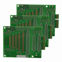
Manufacturer Part Number
AC164139
Description
Graphics Display Prototype Board Graphics
Manufacturer
Microchip Technology
Specifications of AC164139
Main Purpose
LCD Development
Embedded
No
Utilized Ic / Part
PICtail™ Plus Board
Lead Free Status / RoHS Status
Lead free / RoHS Compliant
Secondary Attributes
-
Primary Attributes
-
Lead Free Status / RoHS Status
Lead free / RoHS Compliant
Available stocks
Company
Part Number
Manufacturer
Quantity
Price
Company:

Part Number:
AC164139
Manufacturer:
Microchip Technology
Quantity:
135


PIC24FJ256DA210 FAMILY
REGISTER 23-4:
DS39969B-page 330
bit 15
bit 7
Legend:
R = Readable bit
-n = Value at POR
bit 15
bit 14-13
bit 12-8
bit 7
bit 6-5
bit 4-0
Note 1:
CH0NB
CH0NA
R/W-0
R/W-0
2:
Combinations not shown here (11100 to 11110) are unimplemented; do not use.
Channel 0 positive inputs, AN16 through AN23, are not available on 64-pin devices (PIC24FJXXXDAX06).
CH0NB: Channel 0 Negative Input Select for MUX B Multiplexer Setting bit
1 = Channel 0 negative input is AN1
0 = Channel 0 negative input is V
Unimplemented: Read as ‘0’
CH0SB<4:0>: Channel 0 Positive Input Select for MUX B
Other = Not available; do not use
11111 = No channel used; all inputs are floating; used for CTMU
11011 = Channel 0 positive input is the band gap divided-by-six reference (V
11010 = Channel 0 positive input is the core voltage (V
11001 = Channel 0 positive input is the band gap reference (V
11000 = Channel 0 positive input is the band gap divided-by-two reference (V
10111 = Channel 0 positive input is AN23
.
.
.
00001 = Channel 0 positive input is AN1
00000 = Channel 0 positive input is AN0
CH0NA: Channel 0 Negative Input Select for MUX A Multiplexer Setting bit
1 = Channel 0 negative input is AN1
0 = Channel 0 negative input is V
Unimplemented: Read as ‘0’
CH0SA<4:0>: Channel 0 Positive Input Select for MUX
Other = Not available; do not use
11111 = No Channel used; all inputs are floating; used for CTMU
11011 = Channel 0 positive input is the band gap divided-by-six reference (V
11010 = Channel 0 positive input is the core voltage (V
11001 = Channel 0 positive input is the band gap reference (V
11000 = Channel 0 positive input is the band gap divided-by-two reference (V
10111 = Channel 0 positive input is AN23
.
.
.
00001 = Channel 0 positive input is AN1
00000 = Channel 0 positive input is AN0
U-0
U-0
—
—
AD1CHS: A/D INPUT SELECT REGISTER
W = Writable bit
‘1’ = Bit is set
U-0
U-0
—
—
CH0SB4
CH0SA4
R/W-0
R/W-0
R
R
-
-
(1)
(1)
(2)
(2)
U = Unimplemented bit, read as ‘0’
‘0’ = Bit is cleared
CH0SB3
CH0SA3
R/W-0
R/W-0
(1)
(1)
CAP
(1)
CAP
(1)
)
)
CH0SB2
CH0SA2
R/W-0
R/W-0
BG
BG
)
)
(1)
(1)
2010 Microchip Technology Inc.
x = Bit is unknown
CH0SB1
CH0SA1
R/W-0
R/W-0
BG
BG
BG
BG
/6)
/6)
/2)
/2)
(1)
(1)
CH0SB0
CH0SA0
R/W-0
R/W-0
bit 8
bit 0
(1)
(1)
Related parts for AC164139
Image
Part Number
Description
Manufacturer
Datasheet
Request
R

Part Number:
Description:
Manufacturer:
Microchip Technology Inc.
Datasheet:
Part Number:
Description:
Manufacturer:
Microchip Technology Inc.
Datasheet:
Part Number:
Description:
Manufacturer:
Microchip Technology Inc.
Datasheet:
Part Number:
Description:
Manufacturer:
Microchip Technology Inc.
Datasheet:
Part Number:
Description:
Manufacturer:
Microchip Technology Inc.
Datasheet:
Part Number:
Description:
Manufacturer:
Microchip Technology Inc.
Datasheet:
Part Number:
Description:
Manufacturer:
Microchip Technology Inc.
Datasheet:
Part Number:
Description:
Manufacturer:
Microchip Technology Inc.
Datasheet: