AC164139 Microchip Technology, AC164139 Datasheet - Page 211
AC164139
Manufacturer Part Number
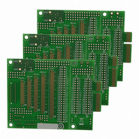
AC164139
Description
Graphics Display Prototype Board Graphics
Manufacturer
Microchip Technology
Specifications of AC164139
Main Purpose
LCD Development
Embedded
No
Utilized Ic / Part
PICtail™ Plus Board
Lead Free Status / RoHS Status
Lead free / RoHS Compliant
Secondary Attributes
-
Primary Attributes
-
Lead Free Status / RoHS Status
Lead free / RoHS Compliant
Available stocks
Company
Part Number
Manufacturer
Quantity
Price
Company:

Part Number:
AC164139
Manufacturer:
Microchip Technology
Quantity:
135


15.0
The Serial Peripheral Interface (SPI) module is a
synchronous serial interface useful for communicating
with other peripheral or microcontroller devices. These
peripheral devices may be serial EEPROMs, shift
registers, display drivers, A/D Converters, etc. The SPI
module is compatible with the SPI and SIOP Motorola
interfaces. All devices of the PIC24FJ256DA210 family
include three SPI modules.
The module supports operation in two buffer modes. In
Standard mode, data is shifted through a single serial
buffer. In Enhanced Buffer mode, data is shifted
through an 8-level FIFO buffer.
2010 Microchip Technology Inc.
Note:
Note:
SERIAL PERIPHERAL
INTERFACE (SPI)
This data sheet summarizes the features
of this group of PIC24F devices. It is not
intended to be a comprehensive reference
source. For more information, refer to the
“PIC24F
Section 23. “Serial Peripheral Interface
(SPI)” (DS39699). The information in this
data sheet supersedes the information in
the FRM.
Do not perform read-modify-write opera-
tions (such as bit-oriented instructions) on
the SPIxBUF register in either Standard or
Enhanced Buffer mode.
Family
Reference
Manual”,
PIC24FJ256DA210 FAMILY
®
The module also supports a basic framed SPI protocol
while operating in either Master or Slave mode. A total
of four framed SPI configurations are supported.
The SPI serial interface consists of four pins:
• SDIx: Serial Data Input
• SDOx: Serial Data Output
• SCKx: Shift Clock Input or Output
• SSx: Active-Low Slave Select or Frame
The SPI module can be configured to operate using 2,
3 or 4 pins. In the 3-pin mode, SSx is not used. In the
2-pin mode, both SDOx and SSx are not used.
Block diagrams of the module in Standard and
Enhanced modes are shown in Figure 15-1 and
Figure 15-2.
Synchronization I/O Pulse
Note:
In this section, the SPI modules are
referred to together as SPIx or separately
as SPI1, SPI2 or SPI3. Special Function
Registers will follow a similar notation. For
example, SPIxCON1 and SPIxCON2 refer
to the control registers for any of the 3 SPI
modules.
DS39969B-page 211
Related parts for AC164139
Image
Part Number
Description
Manufacturer
Datasheet
Request
R

Part Number:
Description:
Manufacturer:
Microchip Technology Inc.
Datasheet:
Part Number:
Description:
Manufacturer:
Microchip Technology Inc.
Datasheet:
Part Number:
Description:
Manufacturer:
Microchip Technology Inc.
Datasheet:
Part Number:
Description:
Manufacturer:
Microchip Technology Inc.
Datasheet:
Part Number:
Description:
Manufacturer:
Microchip Technology Inc.
Datasheet:
Part Number:
Description:
Manufacturer:
Microchip Technology Inc.
Datasheet:
Part Number:
Description:
Manufacturer:
Microchip Technology Inc.
Datasheet:
Part Number:
Description:
Manufacturer:
Microchip Technology Inc.
Datasheet: