AC164139 Microchip Technology, AC164139 Datasheet - Page 325
AC164139
Manufacturer Part Number
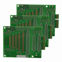
AC164139
Description
Graphics Display Prototype Board Graphics
Manufacturer
Microchip Technology
Specifications of AC164139
Main Purpose
LCD Development
Embedded
No
Utilized Ic / Part
PICtail™ Plus Board
Lead Free Status / RoHS Status
Lead free / RoHS Compliant
Secondary Attributes
-
Primary Attributes
-
Lead Free Status / RoHS Status
Lead free / RoHS Compliant
Available stocks
Company
Part Number
Manufacturer
Quantity
Price
Company:

Part Number:
AC164139
Manufacturer:
Microchip Technology
Quantity:
135


23.0
The 10-bit A/D Converter has the following key
features:
• Successive Approximation (SAR) conversion
• Conversion speeds of up to 500 ksps
• 24 analog input pins (PIC24FJXXXDAX10
• External voltage reference input pins
• Internal band gap reference inputs
• Automatic Channel Scan mode
• Selectable conversion trigger source
• 32-word conversion result buffer
• Selectable Buffer Fill modes
• Four result alignment options
• Operation during CPU Sleep and Idle modes
On all PIC24FJ256DA210 family devices, the 10-bit
A/D Converter has 24 analog input pins, designated
AN0 through AN23. In addition, there are two analog
input pins for external voltage reference connections
(V
may be shared with other analog input pins.
2010 Microchip Technology Inc.
Note:
devices) and 16 analog input pins
(PIC24FJXXXDAX06 devices)
REF
+ and V
10-BIT HIGH-SPEED A/D
CONVERTER
This data sheet summarizes the features
of this group of PIC24F devices. It is not
intended to be a comprehensive reference
source. For more information, refer to the
“PIC24F
Section 17. “10-Bit A/D Converter”
(DS39705). The information in this data
sheet supersedes the information in the
FRM.
REF
-). These voltage reference inputs
Family
Reference
Manual”,
PIC24FJ256DA210 FAMILY
A block diagram of the A/D Converter is shown in
Figure 23-1.
To perform an A/D conversion:
1.
2.
Configure the A/D module:
a)
b)
c)
d)
e)
f)
g)
Configure the A/D interrupt (if required):
a)
b)
Configure the port pins as analog inputs
and/or select band gap reference inputs
(ANCFG registers).
Select the voltage reference source to
match the expected range on analog inputs
(AD1CON2<15:13>).
Select the analog conversion clock to
match the desired data rate with the
processor clock (AD1CON3<7:0>).
Select the appropriate sample/conversion
sequence
AD1CON3<12:8>).
Select how the conversion results are
presented in the buffer (AD1CON1<9:8>).
Select the interrupt rate (AD1CON2<6:2>).
Turn on the A/D module (AD1CON1<15>).
Clear the AD1IF bit.
Select the A/D interrupt priority.
(AD1CON1<7:5>
DS39969B-page 325
and
Related parts for AC164139
Image
Part Number
Description
Manufacturer
Datasheet
Request
R

Part Number:
Description:
Manufacturer:
Microchip Technology Inc.
Datasheet:
Part Number:
Description:
Manufacturer:
Microchip Technology Inc.
Datasheet:
Part Number:
Description:
Manufacturer:
Microchip Technology Inc.
Datasheet:
Part Number:
Description:
Manufacturer:
Microchip Technology Inc.
Datasheet:
Part Number:
Description:
Manufacturer:
Microchip Technology Inc.
Datasheet:
Part Number:
Description:
Manufacturer:
Microchip Technology Inc.
Datasheet:
Part Number:
Description:
Manufacturer:
Microchip Technology Inc.
Datasheet:
Part Number:
Description:
Manufacturer:
Microchip Technology Inc.
Datasheet: