AC164139 Microchip Technology, AC164139 Datasheet - Page 309
AC164139
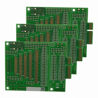
Manufacturer Part Number
AC164139
Description
Graphics Display Prototype Board Graphics
Manufacturer
Microchip Technology
Specifications of AC164139
Main Purpose
LCD Development
Embedded
No
Utilized Ic / Part
PICtail™ Plus Board
Lead Free Status / RoHS Status
Lead free / RoHS Compliant
Secondary Attributes
-
Primary Attributes
-
Lead Free Status / RoHS Status
Lead free / RoHS Compliant
Available stocks
Company
Part Number
Manufacturer
Quantity
Price
Company:

Part Number:
AC164139
Manufacturer:
Microchip Technology
Quantity:
135


REGISTER 22-5:
2010 Microchip Technology Inc.
bit 15
bit 7
Legend:
R = Readable bit
-n = Value at POR
bit 15-10
bit 9
bit 8
bit 7
bit 6
bit 5
bit 4
bit 3
bit 2
DPCLKPOL
R/W-0
U-0
—
Unimplemented: Read as ‘0’
DPPINOE: Display Pin Output Pad Enable bit
DPPINOE is the master output enable and must be set to allow GDBEN<15:0>, DPENOE,
DPPWROE, DPVSOE and DPHSOE to enable the associated pads
1 = Enable display output pads
0 = Disable display output signals as set by GDBEN<15:0>
Pins used by the signals are assigned to the next enabled module that uses the same pins.
For data signals, GDBEN<15:0> can be used to disable or enable specific data signals while
DPPINOE is set.
DPPOWER: Display Power-up Power-Down Sequencer Control bit
Refer to the “PIC24F Family Reference Manual”, Section 43. “Graphics Controller Module (GFX)”
for details.
1 = Set Display Power Sequencer Control port (GPWR) to ‘1’
0 = Set Power Control Sequencer signal (GPWR) ‘0’
DPCLKPOL: Display Glass Clock (GCLK) Polarity bit
1 = Display latches data on the positive edge of GCLK
0 = Display latches data on the negative edge of GCLK
DPENPOL: Display Enable Signal (GEN) Polarity bit
For TFT mode (DPMODE (G1CON2<2:0>) = 001):
1 = Active-high (GEN)
0 = Active-low (GEN)
For STN mode (DPMODE (G1CON2<2:0>) = 010 or 011):
1 = GEN connects to the shift clock input of the display (Shift Clock mode)
0 = GEN connects to the MOD input of the display (Line/Frame Toggle mode)
DPVSPOL: Display Vertical Synchronization (V
1 = Active-high (V
0 = Active-low (V
DPHSPOL: Display Horizontal Synchronization (HSYNC) Polarity bit
1 = Active-high (HSYNC)
0 = Active-low (HSYNC)
DPPWROE: Display Power-up/Power-Down Sequencer Control port (GPWR) enable bit
1 = GPWR port is enabled (pin controlled by the DPPOWER bit (G1CON3<8>))
0 = GPWR port is disabled (pin can be used as an ordinary I/O)
DPENOE: Display Enable Port Enable bit
1 = GEN port is enabled
0 = GEN port is disabled
DPENPOL
R/W-0
U-0
—
G1CON3: DISPLAY CONTROL REGISTER 3
W = Writable bit
‘1’ = Bit is set
SYNC
DPVSPOL
SYNC
R/W-0
U-0
—
)
)
PIC24FJ256DA210 FAMILY
DPHSPOL
R/W-0
U-0
—
SYNC
U = Unimplemented bit, read as ‘0’
DPPWROE
‘0’ = Bit is cleared
R/W-0
) Polarity bit
U-0
—
DPENOE
R/W-0
U-0
—
x = Bit is unknown
DPPINOE
DPVSOE
R/W-0
R/W-0
DS39969B-page 309
DPPOWER
DPHSOE
R/W-0
R/W-0
bit 8
bit 0
Related parts for AC164139
Image
Part Number
Description
Manufacturer
Datasheet
Request
R

Part Number:
Description:
Manufacturer:
Microchip Technology Inc.
Datasheet:
Part Number:
Description:
Manufacturer:
Microchip Technology Inc.
Datasheet:
Part Number:
Description:
Manufacturer:
Microchip Technology Inc.
Datasheet:
Part Number:
Description:
Manufacturer:
Microchip Technology Inc.
Datasheet:
Part Number:
Description:
Manufacturer:
Microchip Technology Inc.
Datasheet:
Part Number:
Description:
Manufacturer:
Microchip Technology Inc.
Datasheet:
Part Number:
Description:
Manufacturer:
Microchip Technology Inc.
Datasheet:
Part Number:
Description:
Manufacturer:
Microchip Technology Inc.
Datasheet: