HFBR-0564 Avago Technologies US Inc., HFBR-0564 Datasheet - Page 3
HFBR-0564
Manufacturer Part Number
HFBR-0564
Description
Fiber Optics, Evaluation Kit
Manufacturer
Avago Technologies US Inc.
Datasheet
1.HFBR-0562.pdf
(14 pages)
Specifications of HFBR-0564
Silicon Manufacturer
Avago
Silicon Core Number
HFBR-591xE
Kit Application Type
Communication & Networking
Application Sub Type
MT-RJ Gigabit Ethernet Transceiver
Main Purpose
Interface, Ethernet
Embedded
No
Utilized Ic / Part
HFCT-591xE, HFBR-591xE
Primary Attributes
MT-RJ Gigabit, Multimode and Singlemode Applications
Secondary Attributes
MT-RJ Fiber Connector Interface
Operating Voltage
3.3 V
Description/function
Fiber Optic Kit
Lead Free Status / RoHS Status
Lead free / RoHS Compliant
For Use With/related Products
HFBR-591x, HFCT-591
Lead Free Status / RoHS Status
Lead free / RoHS Compliant, Contains lead / RoHS non-compliant


Signal Detect
The signal detect circuit works by
sensing the peak level of the received
signal and comparing this level to a
reference level. The signal detect is a
single ended output and is compat-
ible with TTL and CMOS levels. No
external termination is required.
Data Outputs
The receiver DATA and /DATA provide
PECL output levels. These outputs
are PECL compatible and are DC
coupled. Both outputs should be
terminated correctly. Refer to the
‘Termination Schemes’ section for
more detail about recommended
Figure 2a. Typical HFBR-591xE receiver output at +25° C, +3.3 V
termination techniques. Under loss
of light conditions the Data outputs
will switch randomly.
It is recommended that the Receiver
outputs be connected to 50 W trans-
mission lines. Refer to the ‘Board
Layout’ section for additional rec-
ommended PC board layout tech-
niques.
Figure 2a shows a typical HFBR-591xE
receiver data output waveform.
Figure 2b shows a typical HFCT-591xE
receiver data output waveform.
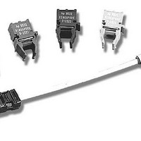
Test Fixture
The Small Form Factor (SFF) trans-
Figure 2b. Typical HFCT-591xE receiver output at +25° C, +3.3 V
ceiver test fixture, shown in Figure 3,
is available for easy test and evalua-
tion purposes.
It has a four layer FR-4 printed circuit
board with ground planes on both
sides. It is designed to be footprint
compatible for all single and multi -
mode Gigabit Ethernet variants.
Figure 3. Test fixture
3
Related parts for HFBR-0564
Image
Part Number
Description
Manufacturer
Datasheet
Request
R

Part Number:
Description:
Fiber Optic Transmitters, Receivers, Transceivers 1300nm 155MBd 16-pin DIP ST Rx
Manufacturer:
Avago Technologies US Inc.

Part Number:
Description:
FIBER OPTIC TX 125 MBD 650N
Manufacturer:
Avago Technologies US Inc.
Datasheet:

Part Number:
Description:
Fiber Optic Evaluation Kit
Manufacturer:
Avago Technologies US Inc.
Datasheet:

Part Number:
Description:
RECEIVER FIBER OPTIC ST 266MBD
Manufacturer:
Avago Technologies US Inc.
Datasheet:

Part Number:
Description:
RCVR OPT HI SPEED VERS LINK HORZ
Manufacturer:
Avago Technologies US Inc.
Datasheet:

Part Number:
Description:
RCVR OPT HI SPEED VERS LINK VERT
Manufacturer:
Avago Technologies US Inc.
Datasheet:

Part Number:
Description:
TXRX OPTICAL 850NM VCSEL MT-RJ
Manufacturer:
Avago Technologies US Inc.
Datasheet:

Part Number:
Description:
TXRX MM SFP LC CONN BAIL DELATCH
Manufacturer:
Avago Technologies US Inc.
Datasheet:

Part Number:
Description:
TXRX MMF SFP GBE/FC BAIL DELATCH
Manufacturer:
Avago Technologies US Inc.
Datasheet:

Part Number:
Description:
XMITTER FIBER OPTIC 266MBD ST
Manufacturer:
Avago Technologies US Inc.
Datasheet:

Part Number:
Description:
OPTOCOUPLER GATE DRV 2A 16-SOIC
Manufacturer:
Avago Technologies US Inc.
Datasheet:
Part Number:
Description:
OPTOCOUPLER 2CH 2.5A 16-SOIC
Manufacturer:
Avago Technologies US Inc.
Datasheet:

Part Number:
Description:
OPTOCOUPLER GATE DRV 0.4A 16SOIC
Manufacturer:
Avago Technologies US Inc.
Datasheet:

Part Number:
Description:
OPTOCOUPLER 2.0A 250KHZ 8-DIP
Manufacturer:
Avago Technologies US Inc.
Datasheet:

Part Number:
Description:
OPTOCOUPLER 2.0A 250KHZ GW 8-SMD
Manufacturer:
Avago Technologies US Inc.
Datasheet: