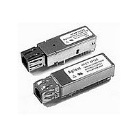
HFBR-0562 Avago Technologies US Inc., HFBR-0562 Datasheet - Page 7

HFBR-0562
Manufacturer Part Number
HFBR-0562
Description
Fiber Optics, Evaluation Kit
Manufacturer
Avago Technologies US Inc.
Specifications of HFBR-0562
Silicon Manufacturer
Avago
Silicon Core Number
HFBR-591xE, HFCT-591xE
Kit Application Type
Communication & Networking
Application Sub Type
MT-RJ Gigabit Ethernet Transceiver
Main Purpose
Interface, Ethernet
Embedded
No
Utilized Ic / Part
HFCT-591xE, HFBR-591xE
Primary Attributes
MT-RJ 1.25Gb Multimode Applications
Secondary Attributes
MT-RJ Fiber Connector Interface
Description/function
Fiber Optic Kit
Lead Free Status / RoHS Status
Lead free / RoHS Compliant
For Use With/related Products
HFBR-591x
Lead Free Status / RoHS Status
Lead free / RoHS Compliant, Contains lead / RoHS non-compliant
7
PCB Footprint and Mechanical
Outline
All dimensions on the circuit board
layout and MT-RJ front panel layout
were taken directly or indirectly
from the joint MSA.
Shown in Figure 8 is the recom-
mended PCB layout for the HFBR/
HFCT-591xE.
The distance from solder posts to
front panel is critical in ensuring
Figure 8. Recommended board layout hole pattern
Dimensions in millimeters (inches)
Notes:
1. This figure describes the recommended circuit board layout for the MT-RJ transceiver pla
2. The hatched areas are keep-out areas reserved for housing standoffs. No metal traces o
3. 2 x 5 transceiver module requires 16 PCB holes (10 I/O pins, 2 solder posts and 4 package
4. Solder posts should be soldered to PCB for mechanical integrity and the holes in the cir
(0.425)
(0.525)
13.34
10.8
0.550 spacing.
connection in keep-out areas.
tabs).
Package grounding tabs should be connected to signal ground.
connected to chassis ground.
(0.299)
(0.276)
7.59
7
(0.118)
3
(1.063)
27
(0.055 ±0.004)
Ø 1.4 ±0.1
(0.236)
(0.118)
6
3
(0.28)
7.11
that the nose shield fits correctly
in the front panel. An important
note is that there is no dimension
that controls the distance from the
solder posts to the edge of the PCB.
This distance is a function of the PCB
material and PCB layout rules. As
long as the solder posts are properly
soldered to the PCB, there is enough
strength in the transceiver port for
repeated connections.
Figure 9 is the package outline
drawing for the HFBR/HFCT-591xE.
(0.18)
4.57
17.78
(0.7)
(0.055 ±0.004)
Ø 1.4 ±0.1
(0.07)
1.778
(0.121)
3.08
7.112
(0.28)
(0.121)
3.08
(0.14)
3.56
Ø 2.29
10.16
(0.09)
(0.4)
(0.378)
9.59
(0.032 ±0.004)
Ø 0.81 ±0.1
(0.55)
13.97
MIN.
Holes For
Housing
Leads
(0.079)
2
(0.055 ±0.
Ø 1.4 ±0.


