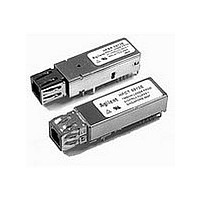
HFBR-0562 Avago Technologies US Inc., HFBR-0562 Datasheet
HFBR-0562
Specifications of HFBR-0562


Related parts for HFBR-0562


HFBR-0562 Summary of contents
Page 1
... PECL logic signals (ECL referenced to a +3.3 V supply) and provides bias and modulation control for the laser. Receiver Section The receiver of the HFBR-5912E includes a GaAs PIN photodiode mounted together with a custom, silicon bipolar transimpedance preamplifier OSA. This OSA is mated to a custom silicon bipolar circuit that provides post- amplification and quantization ...
Page 2
... The multimode port plug is black and the single mode variant is a blue color. Recommended Solder fluxes Solder fluxes used with the HFBR/HFCT-5912E should be water-soluble, organic fluxes. Recommended solder fluxes include Lonco 3355-11 from London Chemical West, Inc. of Burbank, CA, and 100 Flux from Alpha-Metals of Jersey City, NJ ...
Page 3
... Typically show no measurable effect from a 10 V/m field swept from 27 to 1000 MHz applied to the transceiver without a chassis enclosure. AEL Class I, FDA/CDRH HFBR-5912E Accession # 9720151-09 HFCT-5912E Accession # 9521220-20 AEL Class 1, TUV Rheinland of North America HFBR-5912E: Certificate # E9971083.01 HFCT-5912E: Certificate # 933/510817/05 ...
Page 4
... Per the multisource agreement, the HFBR/HFCT-5912E feature a transmit disable function which is a single-ended +3.3 V TTL input signal dc-coupled to pin 8. As for the receiver section internally ac-coupled between the preamplifier and the post- amplifier stages ...
Page 5
... For an optical transmitter device to be eye-safe in the event of a single fault failure, the transmit- ter must either maintain eye-safe operation or be disabled. In the HFBR-5912E there are three key elements to the laser driver safety circuitry: a monitor diode, a window detector circuit, and direct control of the laser bias ...
Page 6
Absolute Maximum Ratings Stresses in excess of the absolute maximum ratings can cause catastrophic damage to the device. Limits apply to each parameter in isolation, all other parameters having values within the recommended operating conditions. It should not be assumed ...
Page 7
... HFBR-5912E, 850 nm VCSEL Transmitter Electrical Characteristics (T = 0°C to +70° Parameter Supply Current Power Dissipation Receiver Electrical Characteristics (T = 0°C to +70° Parameter Supply Current Power Dissipation Data Output Voltage - Low Data Output Voltage - High Data Output Rise Time ...
Page 8
... HFBR-5912E Family, 850 nm VCSEL Transmitter Optical Characteristics (T = 0°C to +70° Parameter Output Optical Power 50/125 µ 0.20 Fiber Output Optical Power 62.5/125 µ 0.275 Fiber Disabled Transmit Output Power Optical Extinction Ratio Center Wavelength Spectral Width - rms Optical Rise/Fall Time ...
Page 9
HFCT-5912E, 1300 nm FP Laser Transmitter Electrical Characteristics (T = 0°C to +70° Parameter Supply Current Power Dissipation Receiver Electrical Characteristics (T = 0°C to +70° 3. ...
Page 10
HFCT-5912E, 1300 nm FP Laser Transmitter Optical Characteristics (T = 0°C to +70° Parameter Output Optical Power 9 µm SMF Output Optical Power 62.5 µm MMF Output Optical Power 50 µm ...
Page 11
Package Grounding Tabs RECEIVER SIGNAL GROUND RECEIVER POWER SUPPLY SIGNAL DETECT RECEIVER DATA OUT BAR RECEIVER DATA OUT Figure 2. Pin Out Table 1. Pin Out Table Pin Symbol Two Mounting The mounting studs are provided for transceiver mechanical attachment ...
Page 12
... VENDORS' MODULES. THE HFBR/HFCT-5912E WILL OPERATE IN BOTH CONFIGURATIONS. ** RECOMMENDED BYPASS CAPACITOR FOR ADDITIONAL LOW FREQUENCY NOISE FILTERING. THE SIGNAL DETECT OUTPUT ON THE HFBR-5912E CONTAINS AN INTERNAL 1.8 k PULL CONFIGURATION AND THEREFORE DOES NOT REQUIRE AN EXTERNAL PULL UP RESISTOR. Figure 3. Recommended Gigabit/sec Ethernet HFBR/HFCT-5912E Fiber-Optic Transceiver and HDMP-1636A/1646A SERDES Integrated Circuit Transceiver Interface and Power Supply Filter Circuits ...
Page 13
... THE 10 I/O PINS, 2 SOLDER POSTS AND 4 PACKAGE GROUNDING TABS ARE TO BE TREATED AS A SINGLE PATTERN. (SEE FIGURE 5 PCB LAYOUT). 4. THE MT-RJ HAS A 750 µm FIBER SPACING. 5. THE MT-RJ ALIGNMENT PINS ARE IN THE MODULE. 6. SEE MT-RJ TRANSCEIVER PIN OUT DIAGRAM FOR DETAILS. Figure 4. Package Outline Drawing of HFBR/HFCT-5912E 13.97 (0.55) MIN. (0.177 ±0.008) ...
Page 14
DIMENSIONS IN MILLIMETERS (INCHES) NOTES: 1. THIS FIGURE DESCRIBES THE RECOMMENDED CIRCUIT BOARD LAYOUT FOR THE MT-RJ ...
Page 15
OF PCB TO MIN. BOTTOM OF OPENING) DIMENSIONS IN MILLIMETERS (INCHES) NOTE: NOSE SHIELD SHOULD BE CONNECTED TO CHASSIS GROUND. Figure 6. Recommended Panel ...
Page 16
... Ordering Information HFBR-5912E - 850 nm VCSEL (Short Wavelength Laser) 1000 Base SX Application HFCT-5912E - 1300 nm FP Laser (Long Wavelength Laser) 1000 Base LX Application www.semiconductor.agilent.com Data subject to change. Copyright © 2000 Agilent Technologies Inc. 5968-9719E (02/00) ...