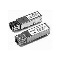
HFBR-0562 Avago Technologies US Inc., HFBR-0562 Datasheet - Page 4

HFBR-0562
Manufacturer Part Number
HFBR-0562
Description
Fiber Optics, Evaluation Kit
Manufacturer
Avago Technologies US Inc.
Specifications of HFBR-0562
Silicon Manufacturer
Avago
Silicon Core Number
HFBR-591xE, HFCT-591xE
Kit Application Type
Communication & Networking
Application Sub Type
MT-RJ Gigabit Ethernet Transceiver
Main Purpose
Interface, Ethernet
Embedded
No
Utilized Ic / Part
HFCT-591xE, HFBR-591xE
Primary Attributes
MT-RJ 1.25Gb Multimode Applications
Secondary Attributes
MT-RJ Fiber Connector Interface
Description/function
Fiber Optic Kit
Lead Free Status / RoHS Status
Lead free / RoHS Compliant
For Use With/related Products
HFBR-591x
Lead Free Status / RoHS Status
Lead free / RoHS Compliant, Contains lead / RoHS non-compliant
4
Edge-mounted SMA connectors are
provided for data inputs and data
outputs. Standard 2 mm sockets are
included for easy connection to DC
power supplies. A sliding switch is
provided for selecting the transmitter
disable function. Gold contact pin
sockets are used to allow inter-
changeability between transceiver
modules while assuring good con-
nection integrity. Ground tab con-
nection holes are provided on the
test fixture for grounding the SFF
Figure 4. Test fixture circuit schematic
V
V
V
V
RD-
RD+
CCT
EET
CCR
EER
SD
CON3
CON4
J1
J2
J4
J3
J5
100 nF
100 nF
C4
C3
C7
100 nF
C9
100 nF
R3
130 R
R4
130 R
+ C10
+ C8
10 F
10 F
GND
V
L1 1 H
L2 1 H
CCR
GND
GND
1
2
3
4
5
U1
V
V
SFF-10
V
V
SD
RD-
RD+
CCT
CCR
EER
CCR
N/C = NOT CONNECTED
transceiver body. Grounding the
transceiver body is recommended
for optimum performance and EMI
compliance. Generous grounding is
provided around the transceiver
footprint using plated through holes.
Figure 4 shows the circuit schematic
for the test fixture. Separate power
supplies are provided to the trans-
mitter and receiver sections, and
the recommended filtering arrange-
ments are also shown.
C1
100 nF
C2
100 nF
V
GND
V
GND
TD+
V
V
T
CCT
CCR
TD-
DIS
EET
CCT
Transmitter Power Supply Filter
Receiver Power Supply Filter
10
9
8
7
6
GND
V
CCT
T
DIS
C11
100 nF
C12
100 nF
SW1
5k1
V
V
CCT
CCT
V
CCT
The signal detect (SD) function is
provided for the user. No termina-
tions are required when monitoring
TTL levels.
The test fixture requires +3.3 V supply
at both V
ter enable/disable switch needs to
be in position 2 for normal operation
and position 1 disables optical data
transmission. The test fixture is rated
for repeated temperature evaluation
from 0° C to +70° C.
Transmit Disable
3k3
3k3
1
2
R1
510R
5k1
CCT
and V
C6
100 nF
C5
100 nF
CCR
CON1
CON2
. The transmit-
RD-
TD+


