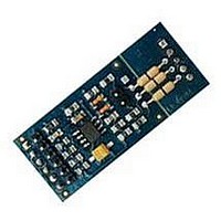
FLEX104 EVIDENCE, FLEX104 Datasheet - Page 29

FLEX104
Manufacturer Part Number
FLEX104
Description
Development Tools & Eval/Demo Boards
Manufacturer
EVIDENCE
Datasheet
1.FLEX103.pdf
(41 pages)
Specifications of FLEX104
Silicon Manufacturer
Microchip
Application Sub Type
FLEX Multibus RS485 Module
Kit Application Type
Communication & Networking
Kit Contents
Board
Supply Voltage Range
7V To 12V, 9V To 36V
Lead Free Status / RoHS Status
Lead free / RoHS Compliant
Multibus base board connectors
The Multibus base board exports the outputs of each module using a set of clamps
which are located on one side of the board (in Figure 3.17, they are named MORS1 to
MORS6). The only exception is the ethernet module, which directly communicate using
the RJ45 connector which is located on the board (please note that the connector is not
solded on the board by default).
appear in Figure 3.17.
Connector 1 (MORS1) Is a 5 pin connector which can be used for the serial lines
connected using the first serial module. The various pins have a different meaning
depending on the serial module which is hosted on the board. In particular:
Connector 3 (MORS3) Is a 3 pin connector which can be used for the serial lines
connected using the second serial module. The various pins have a different meaning
depending on the serial module which is hosted on the board. In particular:
The following paragraphs describe the meaning of the connectors, in the order they
• If the TTL UART or RS232 module is connected, the meaning of the five pins is
• If the RS422 is connected, the meaning of the five pins is the following: 1 - 485+;
• If the RS485 module is connected, the meaning of the five pins is the following: 2
• If the TP-UART module is connected, the meaning of the five pins is the following:
• If the TTL UART or RS232 module is connected, the meaning of the five pins is
• If the RS485 module is connected, the meaning of the five pins is the following: 1
Table 3.7: The table shows the jumper settings for the SPI chip select of Slot 6.
the following: 1 - CTS; 2 - RX; 3 - TX; 4 - RTS; 5 - GND;
2 - 485-; 3 - 485+ (2); 4 - 485- (2); 5 - GND;
- 485-; 3 - 485+; 5 - GND;
2 - A TP; 3 - B TP
the following: 1 - RX; 2 - TX; 3 - GND;
- 485-; 2 - 485+; 3 - GND;
JP9 JP8 JP10 Chip select from
1-2
1-2
2-3
2-3
1-2
2-3
x
x
1-2
2-3
x
x
29
SS2(RG9)
SS1(RB2)
RB9
RB8


