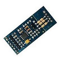
FLEX104 EVIDENCE, FLEX104 Datasheet - Page 13

FLEX104
Manufacturer Part Number
FLEX104
Description
Development Tools & Eval/Demo Boards
Manufacturer
EVIDENCE
Datasheet
1.FLEX103.pdf
(41 pages)
Specifications of FLEX104
Silicon Manufacturer
Microchip
Application Sub Type
FLEX Multibus RS485 Module
Kit Application Type
Communication & Networking
Kit Contents
Board
Supply Voltage Range
7V To 12V, 9V To 36V
Lead Free Status / RoHS Status
Lead free / RoHS Compliant
Jumper
JP3
JP4
JP5
JP6
JP7
JP8
JP9
JP10
JP11
JP12
JP13
JP15, JP16 External Real-time clock (position 1-2)
JP17
Table 3.2: Available configuration jumpers for the FLEX Full board.
Function
Enable the power monitoring leds (closed)
Enable the dsPIC (R) DSC controlled led (closed)
Logical GND (closed) or PE selector (open)
External power supply selector for A/Ds (internal 3.3 V if in
position 1-2)
External power supply selector for A/Ds (internal 0 V if in
position 1-2)
voltage reference selector for the the ICSP programming con-
nector (position 1-2, 5 V, position 2-3, 3.3 V)
PIC18 power supply selector (position 1-2, from USB, position
2-3, from internal power supply)
Master Clear signal switch between dsPIC (R) DSC (position
1-2) and PIC18 (position 2-3)
programming data line switch between dsPIC (R) DSC (posi-
tion 1-2) and PIC18 (position 2-3)
programming clock line switch between dsPIC (R) DSC (posi-
tion 1-2) and PIC18 (position 2-3)
optional RX serial port pull-up resistor (closed)
USB shield to GND (position 1-2) or PE selector (position
2-3)
13


