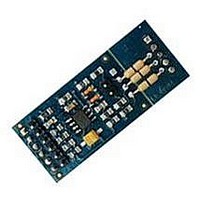
FLEX104 EVIDENCE, FLEX104 Datasheet - Page 19

FLEX104
Manufacturer Part Number
FLEX104
Description
Development Tools & Eval/Demo Boards
Manufacturer
EVIDENCE
Datasheet
1.FLEX103.pdf
(41 pages)
Specifications of FLEX104
Silicon Manufacturer
Microchip
Application Sub Type
FLEX Multibus RS485 Module
Kit Application Type
Communication & Networking
Kit Contents
Board
Supply Voltage Range
7V To 12V, 9V To 36V
Lead Free Status / RoHS Status
Lead free / RoHS Compliant
3 Architecture
Figure 3.12: A typical jumper setting for programming the dsPIC on the FLEX Full.
JP5 (closed) - ground is connected to the PE reference;
JP6 and JP7 (1-2) - A/D converters use VDD and VSS as Vref+ and Vref-;
JP8 (2-3) - the voltage on the ICSP connector is 3.3 V;
JP9 (2-3) - the PIC18 power supply selects the internal power supply;
JP10 (1-2) - the Master Clear signal is connected to the dsPIC;
JP11 (1-2) - the programming data line is connected to the dsPIC;
JP12 (1-2) - the programming clock line is connected to the dsPIC;
JP13 (open) - no RX serial port pull-up resistor;
JP15 and JP16 (2-3) - Real-Time Clock enabled;
JP17 (1-2) USB shield connected to GND.
Programming the PIC18 on the FLEX Full
A basic settings for the jumpers for the FLEX Full in the case the user wants to program
the PIC18 is depicted in Figure 3.13. The Figure highlights the following jumper settings:
JP3 (closed) - the power monitor leds are on when there is power supply;
JP4 (closed) - LEDSYS will be controlled by the dsPIC.
19


