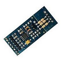
FLEX104 EVIDENCE, FLEX104 Datasheet - Page 20

FLEX104
Manufacturer Part Number
FLEX104
Description
Development Tools & Eval/Demo Boards
Manufacturer
EVIDENCE
Datasheet
1.FLEX103.pdf
(41 pages)
Specifications of FLEX104
Silicon Manufacturer
Microchip
Application Sub Type
FLEX Multibus RS485 Module
Kit Application Type
Communication & Networking
Kit Contents
Board
Supply Voltage Range
7V To 12V, 9V To 36V
Lead Free Status / RoHS Status
Lead free / RoHS Compliant
3 Architecture
Figure 3.13: A typical jumper setting for programming the PIC18 on the FLEX Full.
JP5 (closed) - ground is connected to the PE reference;
JP6 and JP7 (1-2) - A/D converters use VDD and VSS as Vref+ and Vref-;
JP8 (1-2) - the voltage on the ICSP connector is 5 V;
JP9 (2-3) - the PIC18 power supply selects the internal power supply;
JP10 (2-3) - the Master Clear signal is connected to the PIC18;
JP11 (2-3) - the programming data line is connected to the PIC18;
JP12 (2-3) - the programming clock line is connected to the PIC18;
JP13 (open) - no RX serial port pull-up resistor;
JP15 and JP16 (2-3) - Real-Time Clock enabled;
JP17 (1-2) USB shield connected to GND.
3.2 FLEX pinout mapping
1
The next two tables shows the FLEX pinout mappings
3.2.1 FLEX CON5 mappings
1
Thanks to Andrea Bertelli for the Latex tables!
20


