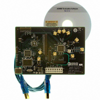
AD9957/PCBZ Analog Devices Inc, AD9957/PCBZ Datasheet - Page 56
AD9957/PCBZ
Manufacturer Part Number
AD9957/PCBZ
Description
D/A Converter Evaluation Board
Manufacturer
Analog Devices Inc
Series
AgileRF™r
Datasheet
1.AD9957BSVZ-REEL.pdf
(64 pages)
Specifications of AD9957/PCBZ
Silicon Manufacturer
Analog Devices
Application Sub Type
Direct Digital Synthesizer
Kit Application Type
Clock & Timing
Silicon Core Number
AD9957
Kit Contents
Board
Main Purpose
Timing: DDS Modulators
Embedded
No
Utilized Ic / Part
AD9957
Primary Attributes
14-Bit DAC, 32-Bit Tuning Word Width
Secondary Attributes
1GHz, Graphical User Interface
Lead Free Status / RoHS Status
Lead free / RoHS Compliant
Available stocks
Company
Part Number
Manufacturer
Quantity
Price
Company:

Part Number:
AD9957/PCBZ
Manufacturer:
LT
Quantity:
962


AD9957
Bit (s)
9
8
7
6
5
4
3
2
1
0
Control Function Register 2 (CFR2)
Address 0x01, four bytes are assigned to this register.
Table 19. Bit Descriptions for CFR2 Register
Bit (s)
31
30
29
28:25
24
23
22
Mnemonic
OSK (Output Shift
Keying) Enable
Select Auto-OSK
Digital Power-
Down
DAC Power-Down
REFCLK Input
Power-Down
Auxiliary DAC
Power-Down
External Power-
Down Control
Auto Power-Down
Enable
SDIO Input Only
LSB First
Mnemonic
Blackfin Interface
Mode Active
Blackfin Bit Order
Blackfin Early
Frame Sync Enable
Open
Enable Profile
Registers as ASF
Source
Internal I/O
Update Active
SYNC_CLK Enable
Description
0: OSK disabled (default).
1: OSK enabled.
Ineffective unless CFR1<9> = 1.
This bit is effective without the need for an I/O update.
0: DAC clock signals and bias circuits are active (default).
1: DAC clock signals and bias circuits are disabled.
This bit is effective without the need for an I/O update.
0: auxiliary DAC clock signals and bias circuits are active (default).
1: auxiliary DAC clock signals and bias circuits are disabled.
0: assertion of the EXT_PWR_DWN pin affects full power-down (default).
1: assertion of the EXT_PWR_DWN pin affects fast recovery power-down.
Ineffective when CFR1<25:24> = 01b.
0: configures the SDIO pin for bidirectional operation; 2-wire serial programming mode (default).
1: configures the serial data I/O pin (SDIO) as an input only pin; 3-wire serial programming mode.
0: configures the serial I/O port for MSB first format (default).
1: configures the serial I/O port for LSB first format.
Description
Valid only when CFR1<25:24> = 00b (quadrature modulation mode).
Valid only when CFR2<31> = 1.
Valid only when CFR2<31> = 1.
Valid only when CFR1<25:24> = 01b (single tone mode) and CFR1<9>=0 (OSK disabled).
This bit is effective without the need for an I/O update.
0: the dual serial port (BFI) configured to be compatible with Blackfin late frame sync operation (default).
1: the dual serial port (BFI) configured to be compatible with Blackfin early frame sync operation.
0: manual OSK enabled (default).
1: automatic OSK enabled.
0: clock signals to the digital core are active (default).
1: clock signals to the digital core are disabled.
0: REFCLK input circuits and PLL are active (default).
1: REFCLK input circuits and PLL are disabled.
0: disable power-down (default).
1: when the TxEnable pin is Logic 0, the baseband signal processing chain is flushed of residual data and
the clocks are automatically stopped. Clocks restart when the TxENABLE pin is a Logic 1.
0: amplitude scale factor bypassed (unity gain).
1: the active profile register determines the amplitude scale factor.
0: Pin D<17:0> configured as an 18-bit parallel port (default).
1: Pin D<5:4> configured as a dual serial port compatible with the Blackfin serial interface. Pin D<17:6>
and Pin D<3:0> become available as a 16-bit GPIO port.
0: the dual serial port (BFI) configured for MSB first operation (default).
1: the dual serial port (BFI) configured for LSB first operation.
0: serial I/O programming is synchronized with external assertion of the I/O_UPDATE pin, which is
configured as an input pin (default).
1: serial I/O programming is synchronized with an internally generated I/O update signal (the internally
generated signal appears at the I/O_UPDATE pin, which is configured as an output pin).
0: the SYNC_CLK pin is disabled; static Logic 0 output.
1: the SYNC_CLK pin generates a clock signal at ¼ f
(default).
Rev. B | Page 56 of 64
SYSCLK
; use of synchronization of the serial I/O port
Related parts for AD9957/PCBZ
Image
Part Number
Description
Manufacturer
Datasheet
Request
R


Part Number:
Description:
±1.7g Dual-Axis IMEMS Accelerometer Evaluation Board
Manufacturer:
Analog Devices Inc
Datasheet:

Part Number:
Description:
Inertial Sensor Evaluation System
Manufacturer:
Analog Devices Inc
Datasheet:
Part Number:
Description:
Manufacturer:
Analog Devices Inc
Datasheet:
Part Number:
Description:
Manufacturer:
Analog Devices Inc
Datasheet:
Part Number:
Description:
Manufacturer:
Analog Devices Inc
Datasheet:
Part Number:
Description:
Manufacturer:
Analog Devices Inc
Datasheet:
Part Number:
Description:
Manufacturer:
Analog Devices Inc
Datasheet:
Part Number:
Description:
Manufacturer:
Analog Devices Inc
Datasheet:
Part Number:
Description:
Manufacturer:
Analog Devices Inc
Datasheet:
Part Number:
Description:
Manufacturer:
Analog Devices Inc
Datasheet:
Part Number:
Description:
Manufacturer:
Analog Devices Inc
Datasheet:
Part Number:
Description:
Manufacturer:
Analog Devices Inc
Datasheet: