AD9957/PCBZ Analog Devices Inc, AD9957/PCBZ Datasheet - Page 44
AD9957/PCBZ
Manufacturer Part Number
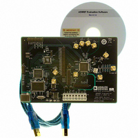
AD9957/PCBZ
Description
D/A Converter Evaluation Board
Manufacturer
Analog Devices Inc
Series
AgileRF™r
Datasheet
1.AD9957BSVZ-REEL.pdf
(64 pages)
Specifications of AD9957/PCBZ
Silicon Manufacturer
Analog Devices
Application Sub Type
Direct Digital Synthesizer
Kit Application Type
Clock & Timing
Silicon Core Number
AD9957
Kit Contents
Board
Main Purpose
Timing: DDS Modulators
Embedded
No
Utilized Ic / Part
AD9957
Primary Attributes
14-Bit DAC, 32-Bit Tuning Word Width
Secondary Attributes
1GHz, Graphical User Interface
Lead Free Status / RoHS Status
Lead free / RoHS Compliant
Available stocks
Company
Part Number
Manufacturer
Quantity
Price
Company:

Part Number:
AD9957/PCBZ
Manufacturer:
LT
Quantity:
962


AD9957
SYNCHRONIZATION EXAMPLE
To accomplish the synchronization of multiple devices provide
each AD9957 with a SYNC_IN signal that is edge aligned across
all the devices. If the SYNC_IN signal is edge aligned at all devices,
and all devices have the same sync receiver delay and sync state
preset value, then they all have matching clock states (that is,
they are synchronized). Figure 59 shows this concept with three
AD9957s in synchronization. One device operates as a master
timing unit with the others synchronized to the master.
The master device must have its SYNC_IN pins included as part
of the synchronization distribution and delay equalization mecha-
nism. This ensures that the master maintains synchronous timing
with the other units.
The synchronization mechanism begins with the clock distribu-
tion and delay equalization block, which ensures that all devices
receive an edge-aligned REFCLK signal. However, even though
the REFCLK signal is edge aligned among all devices, this alone
does not guarantee that the clock state of each internal clock
AT REF_CLK
ALIGNED
INPUTS
EDGE
FPGA
FPGA
FPGA
DELAY EQUALIZATION
CLOCK DISTRIBUTION
(FOR EXAMPLE, AD951x)
Figure 59. Multichip Synchronization Example
AND
DATA
DATA
DATA
Rev. B | Page 44 of 64
SYNC
SYNC
SYNC
NUMBER 1
NUMBER 2
NUMBER 3
AD9957
AD9957
AD9957
IN
IN
IN
SOURCE
REF_CLK
REF_CLK
REF_CLK
CLOCK
SYNC
SYNC
SYNC
OUT
OUT
OUT
generator is coordinated with the others. This is the role of the
synchronization and delay equalization block. This block accepts
the SYNC_OUT signal generated by the master device and
redistributes it to the SYNC_IN input of the slave units (as well
as feeding it back to the master). The goal of the redistributed
SYNC_OUT signal from the master device is to deliver an edge-
aligned SYNC_IN signal to all of the sync receivers.
Assuming that all devices share the same REFCLK edge timing
(due to the clock distribution and delay equalization block) and
that all devices share the same SYNC_IN edge timing (due to
the synchronization and delay equalization block), then all
devices should be generating an internal sync pulse in unison
(assuming all have the same value for the sync receiver delay).
With the further stipulation that all devices have the same sync
state preset value, then the synchronized sync pulses cause all of
the devices to assume the same predefined clock state simultane-
ously. That is, all devices have their internal clocks fully
synchronized.
MASTER DEVICE
AT SYNC_IN
ALIGNED
INPUTS.
EDGE
DELAY EQUALIZATION
(FOR EXAMPLE AD951x)
SYNCHRONIZATION
DISTRIBUTION AND
Related parts for AD9957/PCBZ
Image
Part Number
Description
Manufacturer
Datasheet
Request
R


Part Number:
Description:
±1.7g Dual-Axis IMEMS Accelerometer Evaluation Board
Manufacturer:
Analog Devices Inc
Datasheet:

Part Number:
Description:
Inertial Sensor Evaluation System
Manufacturer:
Analog Devices Inc
Datasheet:
Part Number:
Description:
Manufacturer:
Analog Devices Inc
Datasheet:
Part Number:
Description:
Manufacturer:
Analog Devices Inc
Datasheet:
Part Number:
Description:
Manufacturer:
Analog Devices Inc
Datasheet:
Part Number:
Description:
Manufacturer:
Analog Devices Inc
Datasheet:
Part Number:
Description:
Manufacturer:
Analog Devices Inc
Datasheet:
Part Number:
Description:
Manufacturer:
Analog Devices Inc
Datasheet:
Part Number:
Description:
Manufacturer:
Analog Devices Inc
Datasheet:
Part Number:
Description:
Manufacturer:
Analog Devices Inc
Datasheet:
Part Number:
Description:
Manufacturer:
Analog Devices Inc
Datasheet:
Part Number:
Description:
Manufacturer:
Analog Devices Inc
Datasheet: