603 BG, 603 Datasheet - Page 2
603
Manufacturer Part Number
603
Description
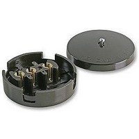
JUNCTION BOX
Manufacturer
BG
Datasheet
1.603.pdf
(2 pages)
Specifications of 603
No. Of Ways
3
Current Rating
30A
Colour
Brown
Mounting Type
Wall
Connector Mounting Orientation
Wall
No. Of Contacts
3
No. Of Positions
3
Available stocks
Company
Part Number
Manufacturer
Quantity
Price
Company:

Part Number:
603
Manufacturer:
MITSUBISH
Quantity:
63 000
Company:
Part Number:
60302504
Manufacturer:
DELPHI
Quantity:
40 000
Company:
Part Number:
60303234
Manufacturer:
DELPHI
Quantity:
40 000
Company:
Part Number:
60303244
Manufacturer:
DELPHI
Quantity:
40 000
Part Number:
6032-35V4.7UF-B
Manufacturer:
AVX
Quantity:
20 000


Installation Information
If in doubt consult a competent electrician.
WIRING
INSTRUCTIONS
JUNCTION BOXES
TECHNICAL HELPLINE: 0800 169 5560
SAFETY WARNING
Before use please read carefully and use in accordance with these safety
wiring instructions.
Before commencing any electrical work ensure the supply is switched off
at the mains, either by switching off the consumer unit or by removing
the appropriate fuse.
Wiring should be in accordance with the latest edition of the IEE
regulations (BS 7671).
JUNCTION BOX – GENERAL ADVICE
The terminals of Junction Boxes can be used for any polarity.
Remove the central screw and remove cover to expose terminals.
In multi-terminal junction boxes, take care to use only one polarity in any
one group of terminals.
Position the way the cable lies, so as to pass through one of the apertures
in the side of the base.
For Selective Entry boxes selecting the apertures to be used by rotating
the guide marked on the lid.
When cable installations are complete, position the cover so as to block off
the cable entry apertures not used in the base and tighten the screw.
Alternatively for non-selective junction boxes the required apertures can be
easily broken away using apair of pliers and with minimal force. Clean
edges to remove any sharp edges.
2.
4-WAY JUNCTION BOX – FOR LIGHTING CIRCUIT
Wire Identification – Twin & Earth Cable
Note - As from 1st April 2004 new colour codes for hard wire installations
was introduced.
EARTH = GREEN/YELLOW Sleeving
BLACK (pre Apr 04) / BLUE (after Apr 04) = NEUTRAL
RED (pre Apr 04) / BROWN (after Apr 04) = LIVE
The ends of the individual conductors should have the insulation removed
by approx. 10mm. Any bare earth conductors should be sleeved to within
10mm of the ends. (These details are for general information only and
conductor lengths may need to be trimmed in certain installations).
For lighting circuits, use sleeving of the appropriate ‘live’ colour to ensure
clear identification of live connections.
See diagram for typical lighting circuit wiring using 4-way junction box.
To prevent fire hazard always use cable of the correct rating and type.
1.
3.
Related parts for 603
Image
Part Number
Description
Manufacturer
Datasheet
Request
R

Part Number:
Description:
MOSFET N-CH DUAL 8V 25MA SOT-363
Manufacturer:
Infineon Technologies
Datasheet:
Part Number:
Description:
MOSFET N-CH DUAL 8V 25MA SOT363
Manufacturer:
Infineon Technologies
Datasheet:
Part Number:
Description:
MOSFET N-CH DUAL 8V SOT-363R
Manufacturer:
Infineon Technologies
Datasheet:
Part Number:
Description:
MOSFET N-CH DUAL 8V 20MA SOT363
Manufacturer:
Infineon Technologies
Datasheet:
Part Number:
Description:
MOSFET N-CH DUAL 8V 20MA SOT-363
Manufacturer:
Infineon Technologies
Datasheet:
Part Number:
Description:
MOSFET N-CH DUAL 8V 25MA SOT363
Manufacturer:
Infineon Technologies
Datasheet:
Part Number:
Description:
MOSFET N-CH DUAL 8V 25MA SOT-363
Manufacturer:
Infineon Technologies
Datasheet:
Part Number:
Description:
MOSFET N-CH DUAL 8V 25MA SOT363
Manufacturer:
Infineon Technologies
Datasheet:
Part Number:
Description:
MOSFET N-CH DUAL 8V 25MA SOT363
Manufacturer:
Infineon Technologies
Datasheet:
Part Number:
Description:
MOSFET N-CH DUAL 8V 25MA SOT363
Manufacturer:
Infineon Technologies
Datasheet:

Part Number:
Description:
IC, 32BIT MCU, PIC32, 80MHZ, BGA-100
Manufacturer:
Microchip Technology
Datasheet:

Part Number:
Description:
Wafer/G2iL+ bumped die on sawn 8 120 m wafer, 7 m Polyimide spacer
Manufacturer:
Philips Semiconductors

Part Number:
Description:
SW PB SPDT BLU CAP SILV SLD LUG
Manufacturer:
NKK Switches
Datasheet:

Part Number:
Description:
SW PB SPDT 3A .315" BLUE CAP PC
Manufacturer:
NKK Switches
Datasheet:
Part Number:
Description:
SW PB SPDT .315" BLUE CAP SLD
Manufacturer:
NKK Switches
Datasheet: