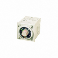
H3CR-F8 AC/DC24 Omron, H3CR-F8 AC/DC24 Datasheet - Page 22

H3CR-F8 AC/DC24
Manufacturer Part Number
H3CR-F8 AC/DC24
Description
TIMER REPEAT CYCLE
Manufacturer
Omron
Series
H3CR-Fr
Datasheet
1.Y92H-7.pdf
(23 pages)
Specifications of H3CR-F8 AC/DC24
Rohs Compliant
YES
Relay Type
Integrated
Function
Repeat Cycle
Circuit
DPDT (2 Form C)
Delay Time
0.05 Sec ~ 30 Hrs
Output Type
Mechanical Relay
Contact Rating @ Voltage
5A @ 250VAC
Voltage - Supply
24VAC/DC
Mounting Type
Socket
Termination Style
8 Pin Socketable
Timing Adjustment Method
Hand Dial
Timing Initiate Method
Input Voltage
Contact Configuration
DPDT
Timing Adjustment
Knob
Relay Mounting
Panel
Lead Free Status / RoHS Status
Lead free / RoHS Compliant
Lead Free Status / RoHS Status
Lead free / RoHS Compliant
Other names
H3CR-F8-AC/DC24
H3CR-F8-AC/DC24
H3CRF8ACDC24
Z2382
H3CR-F8-AC/DC24
H3CRF8ACDC24
Z2382
Correctly Handling Input Signals
Malfunction due to noise may occur if input wiring is placed in the
same duct or conduit as power lines or high-voltage lines. Separate
input wiring from power lines and wire them in a separate system.
Also, use shielded cables, use metal conduits, and keep wiring
distances as short as possible.
Timers with Relays
• Do not connect a load that exceeds contact ratings, such as the
• Continued use with deteriorated performance may ultimately result
• Electrical life depends on the type of load, switching frequency, and
• The surge current depends on the type of load, which also affects
• Arcing when switching and relay heating may result in ignition or
• Contact faults may occur. Do not use the Timer in atmospheres
• The switching capacity for DC voltage loads is lower than that for
Timers with Non-contact Outputs
• Short faults or open faults may occur due to destruction of the
• Short faults or open faults may occur due to destruction of the
Rated current
1 to 3 times the
rated load
Resistive load Solenoid load
switching capacity (contact voltage or contact current). Insulation
faults, contact welding, contact faults, and other failures to achieve
specified performance may occur and the relay may be damaged or
may burn.
in insulation breakdown between circuits or relay burning. The life
of the built-in relay is greatly affected by switching conditions.
Before using the Timer, test operation under actual application
conditions and confirm that the switching frequency presents no
problems in performance.
ambient environment. Observe the following precautions when
using the Timer. When switching a DC load, contact transfer may
cause the contacts to stick or may cause contact failure. Confirm
applicability and consider using a surge absorbing element. When
switching at high frequencies, heat generated by arcing may cause
contacts to melt or may cause metal corrosion. Consider
connecting an arc absorbing element, reducing the switching
frequency, or lowering the humidity.
contact switching frequency and the number of operations. Check
the rated current and the surge current, and design the circuits with
sufficient margin.
Sodium light
explosion. Do not use the Timer in atmospheres subject to
inflammable or explosive gases.
subject to sulfidizing gas, chloride gas, or silicon gas.
AC voltage loads.
output element. Do not use the Timer for a load that exceeds the
rated output current.
output element from reverse electromotive force. When using the
Timer for a DC inductive load, always connect a diode as a
countermeasure against reverse electromotive force.
loads
10 to 20 times
the rated
current
20 to 40 times
the rated load
ALL DIMENSIONS SHOWN ARE IN MILLIMETERS.
To convert millimeters into inches, multiply by 0.03937. To convert grams into ounces, multiply by 0.03527.
Capacitor
http://www.ia.omron.com/
loads
In the interest of product improvement, specifications are subject to change without notice.
5 to 10 times
the rated
current
5 to 15 times
the rated load
Transformer
Motor load
loads
10 to 20 times
the rated
current
1 to 3 times the
rated load
Incandescent
Mercury light
lamp load
loads
Other Precautions
• Confirm that you have the correct model before using it.
• Be sure that all terminals are wired correctly.
• Always test the output status with a tester before using a Timer with
• Leaving the Timer with outputs ON at a high temperature for a long
• Be sure that only a qualified worker (e.g., an electrical engineer)
a built-in keep relay (e.g., the H3CR-H and H3DE-H). Shock
resulting from dropping the Timer during transport or handling may
cause the output contacts to reverse or to be in a neutral status.
time may hasten the degradation of internal parts (such as
electrolytic capacitors). Use the Timer in combination with relays
and avoid leaving the Timer with the output turned ON for an
extended period of time (e.g., for more than a month).
Reference Example (Use the Timer as shown below.)
performs electrical work for the Timer.
(c)Copyright OMRON Corporation 2007 All Rights Reserved.
T
X
2
/b
X
1
T/a
X
1
/a
X
2
X
1
/a
X
Auxiliary relay
(e.g., MY Relays)
C-2


