H3CR-F8 AC/DC24 Omron, H3CR-F8 AC/DC24 Datasheet - Page 15
H3CR-F8 AC/DC24
Manufacturer Part Number
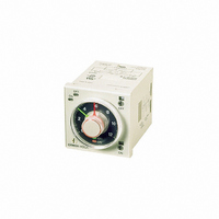
H3CR-F8 AC/DC24
Description
TIMER REPEAT CYCLE
Manufacturer
Omron
Series
H3CR-Fr
Datasheet
1.Y92H-7.pdf
(23 pages)
Specifications of H3CR-F8 AC/DC24
Rohs Compliant
YES
Relay Type
Integrated
Function
Repeat Cycle
Circuit
DPDT (2 Form C)
Delay Time
0.05 Sec ~ 30 Hrs
Output Type
Mechanical Relay
Contact Rating @ Voltage
5A @ 250VAC
Voltage - Supply
24VAC/DC
Mounting Type
Socket
Termination Style
8 Pin Socketable
Timing Adjustment Method
Hand Dial
Timing Initiate Method
Input Voltage
Contact Configuration
DPDT
Timing Adjustment
Knob
Relay Mounting
Panel
Lead Free Status / RoHS Status
Lead free / RoHS Compliant
Lead Free Status / RoHS Status
Lead free / RoHS Compliant
Other names
H3CR-F8-AC/DC24
H3CR-F8-AC/DC24
H3CRF8ACDC24
Z2382
H3CR-F8-AC/DC24
H3CRF8ACDC24
Z2382


■ Ratings
Note: 1. A power supply with a ripple of 20% max. (single-phase power supply with full-wave rectification) can be used with each DC Model.
■ Characteristics
Note: Refer to the Life-test Curve.
Rated supply voltage (See notes 1 and 2.) 100 to 120 VAC (50/60 Hz), 200 to 240 VAC (50/60 Hz), 24 VAC/VDC (50/60 Hz), 48 VDC,
Operating voltage range
No-voltage input (See note 3.)
Power consumption
Control outputs
Accuracy of operating
time
Setting error
Operation start voltage
Influence of voltage
Influence of temperature ±1% FS max. (±1% FS ±10 ms max. in ranges of 0.6 and 1.2 s)
Insulation resistance
Dielectric strength
Impulse withstand
voltage
Noise immunity
Static immunity
Vibration resistance
Shock resistance
Ambient temperature
Ambient humidity
Life expectancy
EMC
Case color
Degree of protection
Weight
2. Do not use an inverter output as the power supply. Refer to Safety Precautions for All Timers for details.
3. For contact input, use contacts which can adequately switch 1 mA at 5 V.
http://www.ia.omron.com/
±0.2% FS max. (±0.2% FS ±10 ms max. in ranges of 0.6 and 1.2 s)
±5% FS ±50 ms max.
30% max. of rated voltage
±0.2% FS max. (±0.2% FS ±10 ms max. in ranges of 0.6 and 1.2 s)
100 MΩ min. (at 500 VDC)
2,000 VAC, 50/60 Hz for 1 min (between current-carrying metal parts and exposed non-current-carrying metal parts)
2,000 VAC, 50/60 Hz for 1 min (between control output terminals and operating circuit)
2,000 VAC, 50/60 Hz for 1 min (between contacts of different polarities)
1,000 VAC, 50/60 Hz for 1 min (between contacts not located next to each other)
3 kV (between power terminals) for 100 to 120 VAC, 200 to 240 VAC, 100 to 125 VDC;
1 kV for 24 VAC/DC, 48 VDC
4.5 kV (between current-carrying terminal and exposed non-current-carrying metal parts) for 100 to 120 VAC, 200 to
240 VAC, 100 to 125 VDC;
1.5 kV for 24 VAC/DC, 48 VDC
±1.5 kV (between power terminals) and ±600 V (between input terminals), square-wave noise by noise simulator
(pulse width: 100 ns/1 μs, 1-ns rise); ±1 kV (between power terminals) for 48 VDC
Malfunction: 8 kV, Destruction:15 kV
Destruction: 10 to 55 Hz with 0.75-mm single amplitude for 2 hrs each in three directions
Malfunction: 10 to 55 Hz with 0.5-mm single amplitude for 10 min each in three directions
Destruction: 980 m/s
Malfunction: 98 m/s
Operating:
Storage:
Operating:
Mechanical: 10 million operations min. (under no load at 1,200 operations/h)
Electrical:
(EMI)
Emission Enclosure:
Emission AC Mains:
(EMS)
Immunity ESD:
Immunity RF-interference from AM Radio Waves:
Immunity RF-interference from Pulse-modulated Radio Waves: IEC61000-4-3: 10 V/m (900±5 MHz) (level 3)
Immunity Conducted Disturbance: IEC61000-4-6:
Immunity Burst:
Immunity Surge:
Light Gray (Munsell 5Y7/1)
IP40 (panel surface)
Approx. 120 g
−10°C to 55°C (with no icing),
−25°C to 65°C (with no icing)
35% to 85%
100,000 operations min. (5 A at 250 VAC, resistive load at 1,200 operations/h) (See note)
100 to 125 VDC
85% to 110% of rated supply voltage
ON-impedance:
ON residual voltage: 1 V max.
OFF impedance:
100 to 120 VAC: approx. 0.23 VA (0.22 W) at 120 VAC
200 to 240 VAC: approx. 0.35 VA (0.3 W) at 240 VAC
24 VAC/DC:
48 VDC:
100 to 125 VDC: approx. 0.5 W at 125 VDC
Contact output: 5 A at 250 VAC/30 VDC, resistive load (cosφ = 1)
2
2
three times each in six directions
three times each in six directions
EN61812-1
EN55011 Group 1 class A
EN55011 Group 1 class A
EN61812-1
IEC61000-4-2:
IEC61000-4-4:
IEC61000-4-5:
approx. 0.17 VA (0.15 W) at 24 VAC
approx. 0.1 W at 24 VDC
approx. 0.18 W at 48 VDC
1 kΩ max.
500 kΩ min.
(c)Copyright OMRON Corporation 2007 All Rights Reserved.
6 kV contact discharge (level 3)
8 kV air discharge (level 3)
IEC61000-4-3: 10 V/m (80 MHz to 1 GHz) (level 3)
10 V (0.15 to 80 MHz) (level 3)
2 kV power-line (level 3)
2 kV I/O signal-line (level 4)
1 kV line to line (level 3)
2 kV line to ground (level 3)
H3CR-H
15
Related parts for H3CR-F8 AC/DC24
Image
Part Number
Description
Manufacturer
Datasheet
Request
R

Part Number:
Description:
RELAY REPEAT CYCLE ANALOG 30HRS
Manufacturer:
Omron
Datasheet:

Part Number:
Description:
RELAY REPEAT CYCLE ANALOG 30HRS
Manufacturer:
Omron
Datasheet:

Part Number:
Description:
Timer; Repeat Cycle; 0.05s-30h; E-Mech; Ctrl-V 100-240AC; 5A@250VAC/30VDC; 8-Pin Octal
Manufacturer:
Omron Automation
Datasheet:
Part Number:
Description:
RELAY REPEAT CYCLE ANALOG 300HRS
Manufacturer:
Omron
Datasheet:
Part Number:
Description:
Timer; Repeat Cycle; 1.2s-300h; E-Mech; Ctrl-V 100-240AC; 5A@250VAC/30VDC; 8-Pin Octal
Manufacturer:
Omron Automation
Datasheet:

Part Number:
Description:
TIMER, RECYCLING
Manufacturer:
Omron
Datasheet:

Part Number:
Description:
Electronic Multifunction Timer
Manufacturer:
Omron
Datasheet:

Part Number:
Description:
RELAY REPEAT CYCLE ANLG 30HRS
Manufacturer:
Omron
Datasheet:
Part Number:
Description:
TIMER REPEAT CYCLE
Manufacturer:
Omron
Datasheet:

Part Number:
Description:
Timer Repeat Cycle
Manufacturer:
Omron
Datasheet:
Part Number:
Description:
G6S-2GLow Signal Relay
Manufacturer:
Omron Corporation
Datasheet:
Part Number:
Description:
Compact, Low-cost, SSR Switching 5 to 20 A
Manufacturer:
Omron Corporation
Datasheet:
Part Number:
Description:
Manufacturer:
Omron Corporation
Datasheet: