SI8435DB-T1-E1 Vishay, SI8435DB-T1-E1 Datasheet
SI8435DB-T1-E1
Specifications of SI8435DB-T1-E1


Related parts for SI8435DB-T1-E1


SI8435DB-T1-E1 Summary of contents
Page 1
... On-Resistance Per Footprint Area 8.48 APPLICATIONS - 7.45 • Low Threshold Load Switch for Portable Devices - Low Power Consumption - Increased Battery Life Device Marking: 8435 xxx = Date/Lot T raceability Code Ordering Information: Si8435DB-T1-E1 (Lead (Pb)-free °C, unless otherwise noted A Symbol ° °C ...
Page 2
... Si8435DB Vishay Siliconix THERMAL RESISTANCE RATINGS Parameter a,b Maximum Junction-to-Ambient Maximum Junction-to-Foot (Drain) Notes: a. Surface Mounted on 1“ x 1“ FR4 board. b. Maximum under Steady State conditions is 72 °C/W. SPECIFICATIONS °C, unless otherwise noted J Parameter Symbol Static Drain-Source Breakdown Voltage ΔV ...
Page 3
... Document Number: 73559 S-82119-Rev. D, 08-Sep-08 Test Conditions ° dI/dt = 100 A/µ °C, unless otherwise noted 1 2.4 3.0 Si8435DB Vishay Siliconix Min. Typ. Max 0.6 1.2 116 174 203 305 = 25 ° 0.0 0.3 0.6 0 Gate-to-Source Voltage (V) GS Transfer Characteristics www.vishay.com Unit 1.2 1 ...
Page 4
... Si8435DB Vishay Siliconix TYPICAL CHARACTERISTICS T 0.12 0. Drain Current ( vs. Drain Current DS(on) 2500 2000 C iss 1500 1000 500 C oss C rss Drain-Source Voltage (V) DS Capacitance Total Gate Charge (nC) g Gate Charge www.vishay.com °C, unless otherwise noted 1 1 4 ...
Page 5
... The power dissipation P junction-to-foot thermal resistance, and is more useful in settling the upper dissipation limit for cases where additional heatsinking is 10 100 used used to determine the current rating, when this rating falls below the package limit. is specified DS(on) Si8435DB Vishay Siliconix 100 T - Case Temperature (° ...
Page 6
... Si8435DB Vishay Siliconix TYPICAL CHARACTERISTICS Duty Cycle = 0.5 0.2 0.1 0.1 0.05 0.02 Single Pulse 0. Normalized Thermal Transient Impedance, Junction-to-Ambient 2 1 Duty Cycle = 0.5 0.2 0.1 0.1 0.05 0.02 Single Pulse 0. Normalized Thermal Transient Impedance, Junction-to-Foot www.vishay.com °C, unless otherwise noted ...
Page 7
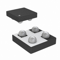
... Diameter E a Millimeters Min. Max. 0.600 0.650 0.260 0.290 0.340 0.360 0.370 0.410 1.520 1.600 1.520 1.600 0.750 0.850 0.370 0.380 Si8435DB Vishay Siliconix Silicon Bump Note Inches Min. Max. 0.0236 0.0256 0.0102 0.0114 0.0134 0.0142 0.0146 0.0161 0.0598 0.0630 0.0598 ...
Page 8
... Vishay product could result in personal injury or death. Customers using or selling Vishay products not expressly indicated for use in such applications their own risk and agree to fully indemnify and hold Vishay and its distributors harmless from and against any and all claims, liabilities, expenses and damages arising or resulting in connection with such use or sale, including attorneys fees, even if such claim alleges that Vishay or its distributor was negligent regarding the design or manufacture of the part ...