N6752A AGILENT TECHNOLOGIES, N6752A Datasheet - Page 13
N6752A
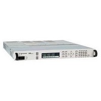
Manufacturer Part Number
N6752A
Description
POWER SUPPLY, BENCH, 50V, 100W
Manufacturer
AGILENT TECHNOLOGIES
Datasheet
1.N6751A.pdf
(20 pages)
Specifications of N6752A
Power Supply Output Type
Variable
No. Of Outputs
1
Output Voltage
50V
Output Current
10A
Power Rating
100W
Input Voltage
100V AC To 240V AC
Length
596.9mm
Width
432.5mm
Height
44.45mm
Lead Free Status / RoHS Status
na


6625A, 6626A, 6628A, 6629A:
These models have 11 internal
registers, which have the
following characteristics:
• Register 0 is recalled
• Register 0 stores: VSET,
• Registers 1-10 save: VSET,
• At power-on, registers 4-10
• Registers 0-3 can only be
• If registers 0-3 are written
• When a register is recalled,
N6700A/B Mainframe:
The N6700A has 11 internal
registers, which have the fol-
lowing characteristics:
• Register 0 is recalled
automatically at power-on.
VRSET, ISET, IRSET, OVSET,
OCP, DLY, and MASK for
all outputs.
VRSET, ISET, IRSET, and
OVSET for all outputs.
are reset to 0 V and minimum
current.
saved once per power-on.
Power needs to be cycled to
re-enable writing to these
non-volatile registers.
to more than once per
power-on cycle, Error 30
“STORE LIMIT” will result.
the outputs are set
sequentially (1,2,3,4).
automatically at power-on
ONLY if the power-on state
is set to RCL0 by sending
the command “OUTPut:
PON:STATe RCL0”.
6621A, 6622A, 6623A, 6624A, 6627A
6625A, 6626A, 6628A, 6629A
N6700A/B
Table 7. Memory STO/RCL States
• All registers (0-10) store:
• At power-on registers 2-10
• The non-volatile registers
• When a register is recalled,
Table 7
ences between the 662xA and
the N6700A/B mainframes
memory states.
VSET, VRSET, ISET, IRSET,
OVSET, OCP, and DLY. The
state of the MASK register
is not stored.
are reset to minimum voltage
and minimum current.
(0-1) can be written to more
than once per power-on cycle.
the outputs are set
sequentially (1,2,3,4).
below shows the differ-
13
Non-Volatile Registers
0
4—Registers 0-3
2—Registers 0-1
Clear Command (CLR)
The Clear “CLR” command is
typically used in systems to
send all devices in the system
to a known state with a single
command. Please see
in the Initial Conditions
section for the “CLR” values.
Volatile Registers
10—Registers 1-10
7—Registers 4-10
9—Registers 2-10
Table 4
Related parts for N6752A
Image
Part Number
Description
Manufacturer
Datasheet
Request
R

Part Number:
Description:
Agilent Tachyon DX4+ (HPFC-5700) Dual-Channel 4-Gb Fibre Channel Controller With The Data Integrity Field (DIF) Feature
Manufacturer:
Agilent Technologies, Inc.
Part Number:
Description:
Manufacturer:
Agilent Technologies, Inc.
Datasheet:
Part Number:
Description:
Manufacturer:
Agilent Technologies, Inc.
Datasheet:
Part Number:
Description:
Manufacturer:
Agilent Technologies, Inc.
Datasheet:
Part Number:
Description:
Manufacturer:
Agilent Technologies, Inc.
Datasheet:
Part Number:
Description:
Manufacturer:
Agilent Technologies, Inc.
Datasheet:
Part Number:
Description:
Manufacturer:
Agilent Technologies, Inc.
Datasheet:
Part Number:
Description:
Manufacturer:
Agilent Technologies, Inc.
Datasheet:
Part Number:
Description:
Manufacturer:
Agilent Technologies, Inc.
Datasheet:
Part Number:
Description:
Manufacturer:
Agilent Technologies, Inc.
Datasheet:
Part Number:
Description:
Manufacturer:
Agilent Technologies, Inc.
Datasheet:
Part Number:
Description:
Manufacturer:
Agilent Technologies, Inc.
Datasheet:
Part Number:
Description:
1.0625 GBd Fibre Channel 10x10 mm QFP Transceiver Chip (Recommend HDMP-1636A for new designs)
Manufacturer:
Agilent Technologies, Inc.
Datasheet:
Part Number:
Description:
Manufacturer:
Agilent Technologies, Inc.
Datasheet:
Part Number:
Description:
1.0625-2.125 GBd Serdes Circuits: SSTL_2
Manufacturer:
Agilent Technologies, Inc.
Datasheet: