PD3-013-42 TRINAMIC, PD3-013-42 Datasheet - Page 3
PD3-013-42
Manufacturer Part Number
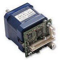
PD3-013-42
Description
STEPPER MOTOR, PANDRIV, 42MM, 0.50NM
Manufacturer
TRINAMIC
Datasheet
1.PD3-013-42.pdf
(27 pages)
Specifications of PD3-013-42
Coil Type
Bipolar
Torque Max
0.49N-m
Current Rating
1A
External Depth
42mm
External Length / Height
49.5mm
External Width
42mm
Holding Torque
0.49N-m
Overall Length
69mm
Steps Per
RoHS Compliant
Svhc
No SVHC (15-Dec-2010)
Rohs Compliant
Yes


TMCM-013 Manual (V1.17 / August 30th, 2006)
3
List of Figures
Figure 3.1: Pinning of TMCM-013 and TMCM-013-LA ........................................................................... 6
Figure 3.2: Dimensions for TMCM-013 ................................................................................................... 7
Figure 3.3: Dimensions for TMCM-013LA............................................................................................... 7
Figure 4.1: Step, Direction and Disable Inputs........................................................................................ 9
Figure 5.1: Assembly of parts................................................................................................................ 10
Figure 5.2: Maximum Supply Voltage regarding Motor Current and Inductivity.................................... 12
Figure 5.3: Connecting Motor and Power Supply ................................................................................. 12
Figure 5.4: Contacts for Step-Direction ................................................................................................. 13
Figure 5.5: Contacts for RS485 with an adapter ................................................................................... 14
Figure 5.6: Connection settings for RS485 ........................................................................................... 14
Figure 6.1: Alarm and GPO ................................................................................................................... 19
Figure 6.2: Step-Direction signals and motor reactions ........................................................................ 23
Figure 6.3: Step and Direction Signal.................................................................................................... 24
Figure 6.4: Firmware update tool .......................................................................................................... 24
Figure 6.5: Reset to factory default ....................................................................................................... 25
Figure 6.6: GPI wiring scheme .............................................................................................................. 25
Figure 6.7: External Changes for act like DC-Motor option................................................................... 26
List of Tables
Table 1.1: Order codes............................................................................................................................ 4
Table 3.1: Pinning of TMCM-013 and TMCM-013-LA............................................................................. 6
Table 4.1: Operational Ratings................................................................................................................ 8
Table 5.1: Maximum Supply Voltage regarding Motor Current and Inductivity..................................... 11
Table 6.1: RS485 Commands ............................................................................................................... 16
Table 6.2: Motor Current Examples ...................................................................................................... 17
Table 6.3: Failure readout in SPI mode................................................................................................. 17
Table 6.4: StallGuard............................................................................................................................. 18
Table 6.5: Limit switch ........................................................................................................................... 18
Table 6.6: Alert adjustments.................................................................................................................. 18
Table 6.7: Output adjustment ................................................................................................................ 19
Table 6.8: I/Os Readout ........................................................................................................................ 19
Table 6.9: Baud rate .............................................................................................................................. 19
Table 6.10: Adjustment of Microstep Resolution................................................................................... 20
Table 6.11: Chopper mode 3 switching velocities................................................................................. 22
Table 6.12: External signals and motor reactions ................................................................................. 22
Table 7.1: Documentation Revisions..................................................................................................... 27
Table 7.2: Firmware Revisions.............................................................................................................. 27
Copyright © 2005, TRINAMIC Motion Control GmbH & Co. KG
Related parts for PD3-013-42
Image
Part Number
Description
Manufacturer
Datasheet
Request
R

Part Number:
Description:
STEPPER MOTOR, PANDRIV, 57MM, 1.63NM
Manufacturer:
TRINAMIC
Datasheet:

Part Number:
Description:
STEPPER MOTOR, PANDRIV, 42MM, 0.50NM
Manufacturer:
TRINAMIC
Datasheet:
Part Number:
Description:
STEPPER MOTOR, PANDRIV, 42MM, 0.50NM
Manufacturer:
TRINAMIC
Datasheet:
Part Number:
Description:
STEPPER MOTOR, PANDRIV, 42MM, 0.50NM
Manufacturer:
TRINAMIC
Datasheet:

Part Number:
Description:
2.54mm Pitch Power Board To Boardconnector
Manufacturer:
DDK Ltd.
Datasheet:
Part Number:
Description:
28mm Nema11 Stepper Motor With Controller Driver Serial Interface
Manufacturer:
ETC-unknow
Datasheet:
Part Number:
Description:
3-way Wilkinson Power Divider
Manufacturer:
Marki Microwave
Datasheet:
Part Number:
Description:
3-way Wilkinson Power Divider
Manufacturer:
Marki Microwave
Datasheet:
Part Number:
Description:
57mm / NEMA23 Stepper Motor with Controller / Driver and Serial Interface
Manufacturer:
TRINAMIC [TRINAMIC Motion Control GmbH & Co. KG.]
Datasheet:
Part Number:
Description:
42mm / NEMA17 Stepper Motor with Controller / Driver and Serial Interface
Manufacturer:
TRINAMIC [TRINAMIC Motion Control GmbH & Co. KG.]
Datasheet:
Part Number:
Description:
57mm/NEMA23 or 60mm/NEMA24 Stepper Motor with Controller/Driver with Encoder and Serial Interface
Manufacturer:
TRINAMIC [TRINAMIC Motion Control GmbH & Co. KG.]
Datasheet:
Part Number:
Description:
60mm/NEMA24 Stepper Motor with Controller/Driver, with Encoder and Serial Interface
Manufacturer:
TRINAMIC [TRINAMIC Motion Control GmbH & Co. KG.]
Datasheet:
Part Number:
Description:
42mm/NEMA17 Stepper Motor with Controller/Driver, Encoderand Serial Interface
Manufacturer:
TRINAMIC [TRINAMIC Motion Control GmbH & Co. KG.]
Datasheet:
Part Number:
Description:
42mm/NEMA17 High Performance BLDC Motor with Controller/Driver and Serial Interface
Manufacturer:
TRINAMIC [TRINAMIC Motion Control GmbH & Co. KG.]
Datasheet:
Part Number:
Description:
57mm diameter BLDC Encoder Motor with Controller/Driver and Serial Interface
Manufacturer:
TRINAMIC [TRINAMIC Motion Control GmbH & Co. KG.]
Datasheet: