S701E15N3S EATON CUTLER HAMMER, S701E15N3S Datasheet - Page 3
S701E15N3S
Manufacturer Part Number
S701E15N3S
Description
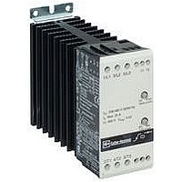
Motor Starter
Manufacturer
EATON CUTLER HAMMER
Datasheet
1.S701E15N3S.pdf
(8 pages)
Specifications of S701E15N3S
No. Of Phases
Three
Power Rating
10hp
Current Rating
15A
Peak Reflow Compatible (260 C)
No
Output Current
15A
Supply Voltage Max
415VAC
Control Voltage Max
480V
Leaded Process Compatible
No
Lead Free Status / RoHS Status
Contains lead / RoHS non-compliant


Current Derating
Operation in ambient temperatures exceeding 40°C [104°F] is
possible if the power dissipation is limited either by reducing
the steady-state current or by reducing the duty cycle of the
soft starter as shown in Table 6.
Table 6. Current Derating
Overload Trip Class
Current Derating for S701_03N3S
Functional Diagram
Example 1
Start with initial torque controlled from the input.
Example 2
Soft start with kick start, initial torque.
Soft stop controlled from the mains input.
Utilization Categories (IEC 947-4-2)
Table 7. Utilization Categories
Effective 01/02
Ambient
Temperature
40° to 50°C
[104° to 122°F]
50° to 60°C
[122° to 140°F]
Item
AC-52a
AC-53a
AC-58a
Mains Ue L1, L2, L3
Control Ue A1A2
Motor Voltage
LED 1
LED 2
10A
10
20
30
Specification
Control of slip-ring motor stators
Control of squirrel cage motor
Control of hermetic refrigerant compressors
with automatic resetting of overload releases
S701_15N3S
15 Amps Max. on-time 15
15 Amps Max. on-time 15
12.5 Amps Continuous or
min. Max. duty cycle 0.65
min. Max. duty cycle 0.8
10 Amps Continuous or
S
15A
15A
12A
10A
S > 10mm, I Max = 3,5 Amps
S < 10mm, I Max = 2,5 Amps
Example 1
S701_25N3S
25 Amps Max. on-time 15
25 Amps Max. on-time 15
min. Max. duty cycle 0.65
min. Max. duty cycle 0.8
20 Amps Continuous or
17 Amps Continuous or
Example 2
25A
25A
20A
15A
Wiring Directions
When using electrical or pneumatic tools for screw termi-
nals, observe maximum torque limits.
Short Circuit Protection
Short circuit protection is divided into two levels —
Type 1 and Type 2.
Type 1 — protects the installation
Type 2 — protects the installation and the
semiconductors inside the motor controller
Short Circuit Protection by Circuit Breaker
A 3-phase motor with a correctly installed and adjusted over-
load relay will not short-circuit totally to earth or between the 3
phases. Part of the winding will normally limit the short circuit
current to a value that will cause instantaneous magnetic trip-
ping of the circuit breaker without damage to the soft starter.
The magnetic trip response current is approximately 11 times
the maximum adjustable current.
Short Circuit Protection by Fuses
Type 1
S701_03N3S — protection max. 25A
S701_15N3S — protection max. 50A
S701_25N3S — protection max. 80A
Type 2
S701_03N3S — protection max. l
S701_15N3S — protection max. l
S701_25N3S — protection max. l
NOTE: S701_25N3S — When protected by a non-time delay
75°C
* UL Tested.
*
*
*
K5 or H class fuse rated 266% of motor FLA, this
device is rated for use on a circuit capable of deliver-
ing not more than 5000 rms symmetrical amperes,
600V maximum.
L1 T1 / L2 T2 / L3 T3 A1 A2 / 11 12
0.75 – 4 mm
[18 – 12 AWG]
1.0 mm
[18 AWG]
0.75 – 6 mm
[18 – 10 AWG]
0.75 – 2.5 mm
[18 – 14 AWG]
0.75 – 6 mm
[18 – 10 AWG]
0.75 – 1.5 mm
[18 – 16 AWG]
Posidrive 1
0.5 Nm max.
[4.4 lb-in max.]
4 mm
0.5 Nm max.
[4.4 lb-in max.]
!
IMPORTANT
2
2
2
2
2
2
2
2
2
t of the fuse 72A
t of the fuse 1800A
t of the fuse 6300A
g
g
g
I/
I/
I/
g
g
g
L/
L/
L/
g
g
g
0.5 – 1.5 mm
[20 – 16 AWG]
0.5 – 0.75 mm
[20 – 18 AWG]
0.5 – 1.5 mm
[20 – 16 AWG]
0.5 – 1.5 mm
[20 – 16 AWG]
0.5 – 1.5 mm
[20 – 16 AWG]
0.5 – 1.5 mm
[20 – 16 AWG]
N/A
3 mm
0.4 Nm max.
[3.5 lb-in max.]
G
G
G 63A T
Pub 49440
2
S
2
2
2
2
2
2
2
S
S
2
3
Related parts for S701E15N3S
Image
Part Number
Description
Manufacturer
Datasheet
Request
R

Part Number:
Description:
HEATSINK CLIP ON UNFINISH TO-220
Manufacturer:
CTS Thermal Management Products

Part Number:
Description:
SUB FEED LUG BLOCK 150A CUTLER HAMMER TYPE BR LOADCENTER
Manufacturer:
EATON CUTLER HAMMER
Part Number:
Description:
Handle Tie Bar For (2) - 1 Pole Type BR Breakers
Manufacturer:
EATON CUTLER HAMMER
Part Number:
Description:
Type CL Breaker 25A/1Pole 120/240V 10K-Classified 1" Ckt Bkr
Manufacturer:
EATON CUTLER HAMMER