S701E15N3S EATON CUTLER HAMMER, S701E15N3S Datasheet - Page 2
S701E15N3S
Manufacturer Part Number
S701E15N3S
Description
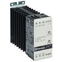
Motor Starter
Manufacturer
EATON CUTLER HAMMER
Datasheet
1.S701E15N3S.pdf
(8 pages)
Specifications of S701E15N3S
No. Of Phases
Three
Power Rating
10hp
Current Rating
15A
Peak Reflow Compatible (260 C)
No
Output Current
15A
Supply Voltage Max
415VAC
Control Voltage Max
480V
Leaded Process Compatible
No
Lead Free Status / RoHS Status
Contains lead / RoHS non-compliant


Pub 49440
Specifications
Table 1. Thermal and Mounting Specifications
* UL Tested.
Table 2. Insulation Specifications
Environment Specifications
EMC
Protection Degree: IP20
Pollution Degree: 3
Table 3. Output Specifications
Table 4. Control Specifications
2
Specification
Power dissipation (max.)
continuous operation
Power dissipation (max.)
intermittent operation
Cooling method
Operating temperature
range, (see Table 6)
Storage temperature
Mounting
Description
Rated insulation voltage
Rated impulse withstand voltage
Installation category
Specification
Operational
Current (max.)
Leakage
Current
Operational
Current (min.)
Max. Motor Size
208 – 230V AC
Max. Motor Size
380 – 415V AC
Max. Motor Size
400 – 480V AC
Max. Motor Size
400 – 600V AC
Control Voltage
C
D
E
G
Pickup Voltage (max.)
Dropout Voltage (min.)
Control Current without operating
Response Time (max.)
Control Current / Power (max.)
S701_03
(0.1 – 0.55 kW)
(0.1 – 1.1 kW)
(0.1 – 1.5 kW)
(0.1 – 1.5 kW)
AC-53a, AC-3
S701_03
AC max.
0.75 hp
50 mA
1.5 hp
5 mA
3.5A
24 – 240
24 – 300
24 – 300
24 – 300
2 hp
2 hp
Natural
[23° to 104°F]
[-4° to 176°F]
Arbitrary
S701_03
4 Watts
4 Watts x
duty cycle
convection
-5° to 40°C
-20° to 80°C
S701_15
(0.1 – 4.0 kW)
(0.1 – 7.5 kW)
(0.1 – 7.5 kW)
(0.1 – 7.5 kW)
AC-53a, AC-3
S701_15
AC max.
5-1/2 hp
50 mA
24 – 240
24 – 480
24 – 480
10 hp
10 hp
10 hp
Specification
Ui 660 Volt
Uimp 4 kVolt
III
4 mA
15A
—
S701_15, S701_25
2 Watts per Amp
2 Watts per Amp x
duty cycle
Natural convention
-5° to 40°C*
[23° to 104°F]
-20° to 80°C
[-4° to 176°F]
Vertical ±30°
Horizontal derate 50%
20.4V AC/DC
15 mA / 2 VA
5V AC/DC
70 ms
1 mA
S701_25
(0.1 – 18.0 kW)
(0.1 – 11.0 kW)
(0.1 – 11.0 kW)
S701_25
(0.1 – 7.5 kW)
AC-53a, AC-3
AC max.
24 – 240
24 – 300
24 – 300
50 mA
10 hp
15 hp
15 hp
25 hp
5 mA
25A
—
Product Selection
Table 5. Product Description and Item Selection
Maintenance
Cooling fins must be kept clean and free from dust. The airflow
must not be blocked.
Wiring Diagram
Figure 5. Wiring Diagram
Terminals 11 and 12 have no connection with the internal circuit.
They are to be used in conjunction with a thermal overload pro-
tection or for other wiring purposes.
NOTE: Use thermal overload protection as required by
Line Voltage
(V AC)
208 – 240
400 – 415
440 – 480
550 – 600
Ramp Up Time
Ramp Down Time
Initial Torque with
Optional Kick Start
Soft Start Controller
the National Electric Code (NEC).
1/L1
2/T1
Line Voltage
C - 208-240 V AC
D - 400-415 V AC
E - 400-480 V AC
G - 550-600 V AC
S 7 0 1 C 15 N 3 S
Item No.
(3.5 Amp)
S701C03N3S
S701D03N3S
S701E03N3S
S701G03N3S
4/T2
3/L2
03 = 3.5 Amps
15 = 15 Amps
25 = 25 Amps
Amperage
Adjustable from 0.5 - 10 seconds
Adjustable from 0.5 - 10 seconds
Adjustable from 0 – 85% of
nominal torque
5/L3
6/T3
Item No.
(15 Amp)
S701C15N3S
S701E15N3S
S701E15N3S
S701G15N3S
A1
Number of Poles
Options
N - No Special Options
B - Braking
Control Options
S - Standard
BP - Aux. Contact
11
Item No.
(25 Amp)
S701C25N3S
S701E25N3S
S701E25N3S
S701G25N3S
Effective 01/02
12
A2
Related parts for S701E15N3S
Image
Part Number
Description
Manufacturer
Datasheet
Request
R

Part Number:
Description:
HEATSINK CLIP ON UNFINISH TO-220
Manufacturer:
CTS Thermal Management Products

Part Number:
Description:
SUB FEED LUG BLOCK 150A CUTLER HAMMER TYPE BR LOADCENTER
Manufacturer:
EATON CUTLER HAMMER
Part Number:
Description:
Handle Tie Bar For (2) - 1 Pole Type BR Breakers
Manufacturer:
EATON CUTLER HAMMER
Part Number:
Description:
Type CL Breaker 25A/1Pole 120/240V 10K-Classified 1" Ckt Bkr
Manufacturer:
EATON CUTLER HAMMER