D4NH3132H Omron, D4NH3132H Datasheet - Page 10
D4NH3132H
Manufacturer Part Number
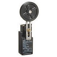
D4NH3132H
Description
LIMIT SWITCH, SPDT-1NO/1NC
Manufacturer
Omron
Series
D4NHr
Datasheet
1.D4NH3132H.pdf
(13 pages)
Specifications of D4NH3132H
Contact Voltage Ac Max
240V
Contact Voltage Dc Max
250V
Contact Current Ac Max
10A
Contact Current Dc Max
2.5A
Switch Terminals
Screw
Contact Configuration
SPDT-1NO / 1NC
Circuitry
SPDT-1NO/1NC
Lead Free Status / RoHS Status
na


Changing the Head Direction
Arm Lever Mounting Position
The arm lever is mounted upwards in the center position before
shipping. To change the position, loosen the arm lever mounting
screw, dismount the arm lever, and mount the arm lever in the left or
right position.
Wiring
Wiring
One-conduit Type (3 Poles)
Two-conduit Type (3 Poles)
A
C
E
[Reference] The crimp terminals shown below are not more than 0.5
A
C
E
• By removing the four screws of the head, the mounting direction of
• Do not insert or remove the Operation Key with the Switch head
• When connecting to the terminals via insulating tube and M3.5
• Do not push crimp terminals into gaps in the case interior. Doing so
• Use crimp terminals not more than 0.5 mm in thickness. Otherwise,
J.S.T. Mfg Co.
the head can be changed. The head can be mounted in four
directions.
Be sure that no foreign material will enter the head during a change
in direction.
removed. Doing so may make it impossible to insert the Operation
Key.
crimp terminals, arrange the crimp terminals as shown below so
that they do not rise up onto the case or the cover. Applicable lead
wire size: AWG20 to AWG18 (0.5 to 0.75 mm
Use lead wires of an appropriate length, as shown below. Not
doing so may result in excess length causing the cover to rise and
not fit properly.
may cause damage or deformation of the case.
they will interfere with other components inside the case.
Manufacture
11
21
33
11
21
33
12
22
34
12
22
34
dz dia.: 3.7 mm
D dia.: 2.9 mm
mm thick.
D
B: 6.6 mm
F: 7.7 mm
B
F
L: 19 mm
I:
D
B
F
t: 0.5 mm
Crimp terminal
42 mm
8.0 mm
FN0.5-3.7 (F Type)
N0.5-3.7 (Straight Type)
Correct
Left hand
E
C
E
D dia.
A
C
B D F
A
B
Type
D
F
Tolerance ±2 mm
28 mm
Tolerance ±2 mm
28 mm
l
33 mm
28 mm
L
Incorrect
42 mm
F
dz dia.
Right hand
Terminal screw
E
2
).
C
A
B D F
B
Tolerance ±2 mm
42 mm
Contact Arrangement
Screw Terminal Type
Connector Type
Socket Tightening (Connector Type)
Conduit Opening
• The following diagrams show the contact arrangements used for
• Applicable socket: XS2F-D421 series (OMRON).
• Refer to the Connector Catalog for details on socket pin numbers
• Turn the socket connector screws by hand and tighten until no
• Make sure that the socket connector is tightened securely.
• Connect a recommended connector to the opening of the conduit
• When using 1/2-14NPT conduits, apply sealing tape between the
• Use a cable with a suitable diameter for the connector.
• Attach and tighten a conduit cap to the unused conduit opening
screw terminal types and connector types.
and lead wire colors.
space remains between the socket and the plug.
Otherwise, the rated degree of protection (IP67) may not be
maintained and vibration may loosen the socket connector.
and tighten the connector to the specified torque. The case may be
damaged if an excessive tightening torque is applied.
connector and conduit opening to maintain the degree of protection
(IP67) of the Switch.
when wiring. Tighten the conduit cap to the specified torque. The
conduit cap is provided with the Switch (2-conduit types).
D4NH-@D@@ (3NC)
D4NH-@B@@ (2NC)
Pin No. (Terminal No.)
11
21
31
11
31
2
1
3
4
12
22
32
12
32
D4NH-9A@@ (1NC/1NO)
D4NH-9E@@ (1NC/1NO (MBB))
D4NH-@C@@ (2NC/1NO)
D4NH-@F@@ (2NC/1NO (MBB))
D4NH-@A@@ (1NC/1NO)
D4NH-@E@@ (1NC/1NO (MBB))
D4NH-9B@@ (2NC)
(1) 11
(3) 31
(1) 11
(3) 33
11
21
33
11
33
12 (2)
32 (4)
12 (2)
34 (4)
12
22
34
12
34
D4NH
10
Related parts for D4NH3132H
Image
Part Number
Description
Manufacturer
Datasheet
Request
R

Part Number:
Description:
LIMIT SWITCH, ROLLER LEVER
Manufacturer:
Omron
Datasheet:

Part Number:
Description:
LIMIT SWITCH, 1WAY, ROLLER ARM
Manufacturer:
Omron
Datasheet:

Part Number:
Description:
LIMIT SW, ADJUSTABLE ROLLER LEVER, SPDT
Manufacturer:
Omron
Datasheet:

Part Number:
Description:
G6S-2GLow Signal Relay
Manufacturer:
Omron Corporation
Datasheet:
Part Number:
Description:
Compact, Low-cost, SSR Switching 5 to 20 A
Manufacturer:
Omron Corporation
Datasheet:
Part Number:
Description:
Manufacturer:
Omron Corporation
Datasheet:
Part Number:
Description:
Manufacturer:
Omron Corporation
Datasheet:
Part Number:
Description:
Manufacturer:
Omron Corporation
Datasheet:
Part Number:
Description:
Manufacturer:
Omron Corporation
Datasheet:
Part Number:
Description:
Manufacturer:
Omron Corporation
Datasheet: