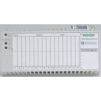
170BNO67100 SQUARE D, 170BNO67100 Datasheet - Page 74
170BNO67100
Manufacturer Part Number
170BNO67100
Description
Programmable Logic Controller
Manufacturer
SQUARE D
Datasheet
1.170BNO67100.pdf
(108 pages)
Specifications of 170BNO67100
Peak Reflow Compatible (260 C)
No
Leaded Process Compatible
No
Lead Free Status / RoHS Status
Contains lead / RoHS non-compliant


Presentation,
description
1
2
3
4
2
74
63 A power splitter box.
Control splitter box.
Connection cable.
Connection control module.
1
3
4
1
2
3
4
5
Advantys
Solution
Parallel interface module STB EPI 1145
Tego
The STB EPI 1145 parallel interface is a component of the Advantys STB island
designed for the remote connection of 8 motor-starters (or 4 motor-starters in both
directions). These TeSys
assistance system.
Tego Power is a modular system to help install TeSys
offering prewired control and power circuits. This Quickfit technology enables cable-
free connections to spring-loaded terminals for TeSys
A) and GV2 M2 motor circuit-breakers.
Tego Power with Quickfit technology enables you to create motor-starter assemblies
up to 15 kW/400 V.
The Tego Power system differentiates the power section from the control section:
b The power kit comprises:
v a specific plate used to assemble 2 to 8 motor-starters.
v two connection modules.
v a power splitter box with a power terminal block.
The contactor for each motor-starter is activated by one of the 8 outputs of the
STB EPI 1145 parallel interface.
b The control kit comprises:
v a control splitter box for the 2 to 8 motor-starters.
v a connection module.
The 2 return outputs of each motor-starter (contactor status, circuit-breaker status)
are connected to 2 of the 16 inputs to the STB EPI 1145 parallel interface.
The STB EPI 1145 parallel interface comprises:
1
Indication
Module status (1)
Module error (2)
Switch position
State of outputs
2
3
4
5
To be ordered separately:
b STB XBA 2000 base width 18.4 mm (0.06"). Includes a location for a customizing
label.
b Optional mechanical keying pin between module and base STB XMP 7700. This
device ensures that the module and its base are properly matched after dismantling
or replacement.
b Sheets of customizing labels: STB XMP 7600.
b A cable between module STB EPI 1145 and the Tego Power block
(1) RDY is on permanently if the module is operational. If RDY is not lit, the PDM is not supplying
(2) If ERR is lit or flashing, the module has an internal error.
(3) S1: output bank 1 (outputs 1 to 4).
Presentation
The Tego Power System
Structure of the Tego Power system
Description
A display block with 8 LEDs indicating the state of the various motor-starters or
output devices.
A location for a customizing label.
A color-coded module identification stripe (black).
A selection switch used to view each motor-starter state.
An HE 10 connector (30-pin) to connect to a Tego Power system via
STB XCA 3002/3003 cables, length 1 m/2 m (1.09/2.18 yd).
power. If RDY flashes, the module is faulty.
For information about the signaling of module and channel states, consult the
hardware components reference guide
from our website www.us.telemecanique.com.
S2: output bank 2 (outputs 5 to 8).
®
Power applications
4
(3)
™
®
Model D motor-starters use the Tego Power installation
STB Distributed I/O
Standard STB EPI 1145 module
Green RDY LED
Red ERR LED
Green S1 and S2 LEDs
Green LEDs O1/5, O2/6, O3/7, O4/8
”
included on the CD-ROM STB SUS 8800 or available
®
®
Model D contactors (9 to 25
Model D motor-starters by
“
System
0
Related parts for 170BNO67100
Image
Part Number
Description
Manufacturer
Datasheet
Request
R

Part Number:
Description:
TRANSFORMR AUTO 115-230VAC 200VA
Manufacturer:
Hammond Manufacturing
Datasheet:


Part Number:
Description:
Pushbutton, Non-Illum'd Red "STOP", Momentary, 1NO-1NC, Square 30mm, 10A, 600V
Manufacturer:
SQUARE D
Datasheet:

Part Number:
Description:
KITS,TWIDO? PROGRAMMABLE CONTROLLERS,KITS,TWIDOPACK STARTER KIT - ADVANCED LEVEL,PROGRAMMABLE CONTROLLERS,TWIDO? PROGRAMMABLE CONTROLLERS ,SQUARE D
Manufacturer:
SQUARE D

Part Number:
Description:
LAMPS,INDICATOR,STACKABLE,LAMPS, STACKABLE INDICATOR,VISUAL INDICATING SIGNALS,XVB SERIES INDICATING BANKS ,SQUARE D
Manufacturer:
SQUARE D
Part Number:
Description:
LAMPS,INDICATOR,STACKABLE,LAMPS, STACKABLE INDICATOR,VISUAL INDICATING SIGNALS,XVB SERIES INDICATING BANKS ,SQUARE D
Manufacturer:
SQUARE D
Datasheet:
Part Number:
Description:
CB ACCESSORY, UNDERVOLTAGE TRIP 48V DC
Manufacturer:
SQUARE D
Datasheet: