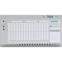
170BNO67100 SQUARE D, 170BNO67100 Datasheet - Page 39

170BNO67100
Manufacturer Part Number
170BNO67100
Description
Programmable Logic Controller
Manufacturer
SQUARE D
Datasheet
1.170BNO67100.pdf
(108 pages)
Specifications of 170BNO67100
Peak Reflow Compatible (260 C)
No
Leaded Process Compatible
No
Lead Free Status / RoHS Status
Contains lead / RoHS non-compliant
STB XSP 3000
Description
(continued)
STB XSP 3010/3020
Advantys
Solution
Digital Input/Output Modules
I/O module bases in 3 widths depending on modules:
Module size
1
2
3
These bases have:
v a place for a customized label STB XMP 6700 (1)
v 4 locations for placing module/base keying pins(1)
Removable connectors
Screw terminals
Spring terminals
These removable connectors have between 5 and 18 possible ways of coding the
module/connector keying pins (1).
Mechanical keying pins and identifiers
These devices ensure that each I/O module, its base and its wiring connectors are
properly matched after dismantling or replacement.
Keying between
module and base (1)
STBXMP7700
Customizing labels STB XMP 6700 make it much easier to recognize I/O modules
and their bases.
External cable shielding connector
This optional device allows quick and easy connection of external cable shielding(1).
Connection and shielding kit
Lateral supports and metal bar, length 1m
Cable clamp size 1 (sachet of 10)
for shielded cable with external diameter 1.5 to 6.5 mm
Cable clamp size 2 (sachet of 10)
for shielded cable with external diameter 5 to 11 mm
Digital input modules and digital output modules (c 24 V, a 115/220 V and 2A relay)
include a ground connection which makes this accessory optional in those cases.
For analog modules, it is advisable to this device as it allows quick and easy
connection of external cable shielding (1).
(1) To find out:
(2) Template file for printing labels on a laser printer (color or black and white) or manual marking
Description (continued)
Mandatory items to be ordered separately
Connector type
(2 connectors per
module)
Optional items to be ordered separately
- the coding of keying pins
- how to use the CEM kit
consult the system planning and installation guide included on the CD-ROM STB SUS 8800
or available on our website www.us.telemecanique.com.
with indelible felt pen: included on the mini CD-ROM supplied with each NIM network interface
module or available from our website www.us.telemecanique.com.
5 pins
STBXTS1110
(sachet of 20)
STBXTS2110
(sachet of 20)
Keying between
module and
connectors (1)
STBXMP7800
™
STB Distributed I/O
Width
13.9 mm (0.547")
18.4 mm (0.72")
28.1 mm (1.10")
6 pins
STBXTS1100
(sachet of 20)
STBXTS2100
(sachet of 20)
Module
identification (2)
STBXMP6700
2
(0.19 to 0.43"
2
(0.06 to 0.25"
Base catalog number
STBXBA1000
STBXBA2000
STBXBA3000
2
)
2
)
Terminals for
grounding kit
18 pins
STBXTS1180
(sachet of 2)
STBXTS2180
(sachet of 2)
Base identification
(2)
STBXMP6700
STBXSP3020
39
0


