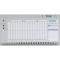
170BNO67100 SQUARE D, 170BNO67100 Datasheet - Page 18

170BNO67100
Manufacturer Part Number
170BNO67100
Description
Programmable Logic Controller
Manufacturer
SQUARE D
Datasheet
1.170BNO67100.pdf
(108 pages)
Specifications of 170BNO67100
Peak Reflow Compatible (260 C)
No
Leaded Process Compatible
No
Lead Free Status / RoHS Status
Contains lead / RoHS non-compliant
1
2
I
interface modules
Description
3
Interface modules with network/bus
address selectors.
1
2
3
NTER
18
B
US
STB NIB 2212/1010
4
5
6
7
8
4
5
6
7
8
(STB Npp 2212
standard module
only)
(STB Npp 2212
standard module
only)
Advantys
Solution
Network Interface Modules
The front panel of the STB Npp 2212/1010 network interface module has the
following features:
1
2
3
4
Indication
Island state: auto-configuration,
operational, error etc.(1)
Power supply: NIM switched on,
internal 5V operational
Module error (2)
1 to 3 LED status indicators
Test mode(3)
5
6
7
8
The network interface modules are supplied with:
b a mini CD-ROM containing documentation in English, label templates and one
exchange file per network type.
b STB XMP 1100 bus termination
They are mounted directly on the DIN rail.
The CD-ROM STB SUS 8800 contains specific documentation for each of the
11 network interface modules in 5 languages. These documents can also be
downloaded from www.us.telemecanique.com.
(1) RUN is on permanently if the module is operational and flashes in different ways in the
(2) ERR is off when the island is OK. Otherwise, ERR flashes or is lit.
(3) Test off: island OK. Test flashing: backup of parameters to internal memory or SIM card in
(4) Pressing the Reset button for 4 seconds restores the island to the factory settings or settings
(5) Firmware update of NIM modules available at www.us.telemecanique.com.
Description
Network interface modules STB Npp 2212/1010
A connector to connect the island to the fieldbus. See photos of different types of
connectors on pages 14 and 15 and characteristics on page 19.
- All NIM modules except I
addressing selectors on the bus or the network.
- I
female connector used to connect the output bus cable.
An external c 24 V power connector for the removable screw-type
(STB XTS 1120) or spring-type (STB XTS 2120) connector.
A display block with LEDs for the various island states on the bus: power,
communication, send/receive data, errors, etc.
A color-coded module identification stripe: yellow.
A screw for releasing the STB Npp 2212/1010 module from the DIN rail.
The NIM can be withdrawn from the island even if the product is assembled:
simply withdraw the PDM then turn this screw a quarter turn.
A slot for a removable SIM card STB XMP 4440 (only on standard NIM modules
STB Npp 2212).
- Standard NIM module: door giving access to the port used to connect an island
setup and configuration PC or an HMI terminal (read/write data), and the Reset
button (4). Can also be used to update the firmware for the network interface
module (5).
- Basic NIM module: door giving access to the port used to connect a PC
(for updating the firmware for the network interface module only) and the
Reset button (4).
other states.
If RUN flashes on start-up, the NIM module is in the auto-configuration phase.
If RUN flashes for a long time, there is a fault on the island. For information about the signaling
of NIM and island states, consult the
network concerned included on the CD-ROM STB SUS 8800 or available from our website
www.us.telemecanique.com.
progress. Test on: island in test mode.
equivalent to content of SIM card.
NTER
B
US
STB NIB 2212/1010
™
STB Distributed I/O
NTER
Basic NIM modules
Green RUN LED
Green PWR LED
Red ERR LED
Depending on bus/network
–
B
“
NETWORK INTERFACE
NETWORK INTERFACE
US NETWORK INTERFACE
module applications guide” for the
modules: A 9-pin SUB-D
Standard NIM modules
Green RUN LED
Green PWR LED
Red ERR LED
Depending on bus/network
Yellow Test LED
: Two rotary node
0


