APDS-9801 Avago Technologies US Inc., APDS-9801 Datasheet - Page 5
APDS-9801
Manufacturer Part Number
APDS-9801
Description
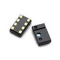
INTEGRATED DIGITAL PS AND ALS
Manufacturer
Avago Technologies US Inc.
Type
Analog Ambient Light Sensor and Digital Proximity Sensorr
Datasheet
1.APDS-9801.pdf
(24 pages)
Specifications of APDS-9801
Peak Wavelength
940 nm
Maximum Light Current
83 uA
Maximum Dark Current
300 nA
Maximum Rise Time
1000 ns
Maximum Fall Time
300 ns
Mounting Style
SMD/SMT
Product
Integrated Ambient Light and Proximity Sensor
Lead Free Status / RoHS Status
Lead free / RoHS Compliant
Lead Free Status / RoHS Status
Lead free / RoHS Compliant, Lead free / RoHS Compliant
Available stocks
Company
Part Number
Manufacturer
Quantity
Price
Company:

Part Number:
APDS-9801
Manufacturer:
LEGERITY
Quantity:
1 043
Company:
Part Number:
APDS-9801
Manufacturer:
Avago Technologies
Quantity:
1 781
Company:
Part Number:
APDS-9801-021
Manufacturer:
AVAGO
Quantity:
20 000


Definition of timing for I
This section will describe the main protocol of the I2C bus. For more details and timing diagrams, please refer to the I
bus specification.
Characteristics of the SDA and SCL bus lines for I
5
SDA
SCL
PARAMETER
SCL clock frequency
Hold time (repeated) START condition.
After this period, the first clock pulse is generated
LOW period of the SCL clock
HIGH period of the SCL clock
Set-up time for a repeated START condition
Data hold time:
Data set-up time
Rise time of both SDA and SCL signals
Fall time of both SDA and SCL signals
Set-up time for STOP condition
Bus free time between a STOP and START
condition
Capacitive load for each bus line
Noise margin at the LOW level for each
connected device (including hysteresis)
Noise margin at the HIGH level for each
connected device (including hysteresis)
t
f
S
t
HD;STA
t
LOW
t
2
r
C devices
t
HD;DAT
t
SU;DAT
t
HIGH
2
C-bus devices
t
f
t
SYMBOL
f
t
t
t
t
t
t
t
t
t
t
C
V
V
SU;STA
SCL
HD;STA
LOW
HIGH
SU;STA
HD;DAT
SU;DAT
r
f
SU;STO
BUF
nL
nH
b
Sr
STANDARD-MODE
MIN.
0
4.0
4.7
4.0
4.7
300
250
–
–
4.0
4.7
–
0.1V
0.2V
BUS
BUS
t
HD;STA
MAX.
100
–
–
–
–
–
–
1000
300
–
–
400
–
–
t
SP
FAST-MODE
MIN.
0
0.6
1.3
0.6
0.6
300
100
–
0.6
1.3
–
0.1V
0.2V
t
SU;STO
BUS
BUS
t
r
P
MAX.
400
–
–
–
–
–
–
300
300
–
–
400
–
–
t
BUF
MSC610
S
UNIT
kHz
Ps
Ps
Ps
Ps
ns
ns
ns
ns
Ps
Ps
pF
V
V
2
C
Related parts for APDS-9801
Image
Part Number
Description
Manufacturer
Datasheet
Request
R

Part Number:
Description:
MINIATURE SURFACE-MOUNT AMBIENT LIGHT PHOTO SENSOR
Manufacturer:
Avago Technologies US Inc.
Datasheet:

Part Number:
Description:
Photodiodes Proximity Sensor
Manufacturer:
Avago Technologies US Inc.
Datasheet:

Part Number:
Description:
IC PROXIMITY SENSOR AMB LT 10QFN
Manufacturer:
Avago Technologies US Inc.
Datasheet:

Part Number:
Description:
AMBIENT LIGHT SENSOR 4CHIPLED
Manufacturer:
Avago Technologies US Inc.
Datasheet:

Part Number:
Description:
Photodiodes Sigl Conditioning IC f/ Opt Proximity Sen
Manufacturer:
Avago Technologies US Inc.
Datasheet:

Part Number:
Description:
Photodiodes Sigl Conditioning IC f/ Opt Proximity Sen
Manufacturer:
Avago Technologies US Inc.
Datasheet:

Part Number:
Description:
AMBIENT LIGHT SENSOR 6CHIPLED
Manufacturer:
Avago Technologies US Inc.
Datasheet:

Part Number:
Description:
AMBIENT LIGHT SENSOR 4CHIPLED
Manufacturer:
Avago Technologies US Inc.
Datasheet:

Part Number:
Description:
AMBIENT LIGHT SENSOR 6CHIPLED
Manufacturer:
Avago Technologies US Inc.
Datasheet:

Part Number:
Description:
AMBIENT LIGHT SENSOR 6CHIPLED
Manufacturer:
Avago Technologies US Inc.
Datasheet:

Part Number:
Description:
OPTOCOUPLER GATE DRV 2A 16-SOIC
Manufacturer:
Avago Technologies US Inc.
Datasheet:
Part Number:
Description:
OPTOCOUPLER 2CH 2.5A 16-SOIC
Manufacturer:
Avago Technologies US Inc.
Datasheet:

Part Number:
Description:
OPTOCOUPLER GATE DRV 0.4A 16SOIC
Manufacturer:
Avago Technologies US Inc.
Datasheet:

Part Number:
Description:
OPTOCOUPLER 2.0A 250KHZ 8-DIP
Manufacturer:
Avago Technologies US Inc.
Datasheet:

Part Number:
Description:
OPTOCOUPLER 2.0A 250KHZ GW 8-SMD
Manufacturer:
Avago Technologies US Inc.
Datasheet: