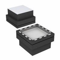
ADIS16060BCCZ Analog Devices Inc, ADIS16060BCCZ Datasheet - Page 11

ADIS16060BCCZ
Manufacturer Part Number
ADIS16060BCCZ
Description
IC GYROSCOPE YAW RATE SPI 16LGA
Manufacturer
Analog Devices Inc
Datasheet
1.ADIS16060PCBZ.pdf
(12 pages)
Specifications of ADIS16060BCCZ
Range °/s
±80°/s
Sensitivity
0.0122°/sec/LSB
Typical Bandwidth
1kHz
Voltage - Supply
4.75 V ~ 5.25 V
Current - Supply
4.3mA
Output Type
SPI
Operating Temperature
-40°C ~ 105°C
Package / Case
16-LGA
No. Of Axes
1
Sensor Case Style
LGA
No. Of Pins
16
Supply Voltage Range
4.75V To 5.25V
Operating Temperature Range
-40°C To +105°C
Msl
MSL 1 - Unlimited
Acceleration Range
2000g
Lead Free Status / RoHS Status
Lead free / RoHS Compliant
For Use With
ADIS16060/PCBZ - BOARD EVAL FOR ADIS16060
Lead Free Status / RoHS Status
Lead free / RoHS Compliant, Lead free / RoHS Compliant
APPLICATIONS INFORMATION
SUPPLY AND COMMON CONSIDERATIONS
Power supply noise and transient behaviors can influence the
accuracy and stability of any sensor-based measurement system.
The ADIS16060 provides 0.2 μF of decoupling capacitance on
the V
power supply of the system, the ADIS16060 may not require
any additional decoupling capacitance for this supply.
SETTING BANDWIDTH
External Capacitor C
chip R
bandwidth of the ADIS16060 rate response. The –3 dB
frequency set by R
and can be well controlled because R
during manufacturing to be 200 kΩ ± 5%. Setting the range
with an external resistor impacts R
In general, an additional hardware or software filter is added to
attenuate high frequency noise arising from demodulation spikes
at the gyro’s 14 kHz resonant frequency. The noise spikes at 14 kHz
can be clearly seen in the power spectral density curve shown in
Figure 14.
INCREASING MEASUREMENT RANGE
Scaling the measurement range requires the addition of a single
resistor, connected across the RATE and FILT pins. The following
equation provides the proper relationship for selecting the
appropriate resistor:
where Δ is the increase in range.
R
R
CC
f
OUT
OUT
OUT
EXT
pin. Depending on the level of noise present in the
resistor to create a low-pass filter to limit the
=
=
=
(
200
(
(
2
200
200
Δ
×
−
π
kΩ
kΩ
kΩ
1
OUT
×
R
OUT
×
+
and C
OUT
1
R
R
is used in combination with the on-
EXT
EXT
×
C
OUT
)
)
OUT
is
)
OUT
OUT
as follows:
has been trimmed
Rev. 0 | Page 11 of 12
DYNAMIC DIGITAL SENSITIVITY SCALING
This device supports in-system, dynamic, digital sensitivity scaling.
TEMPERATURE MEASUREMENTS
When using the temperature sensor, an acquisition time of
greater than 40 μs helps to ensure proper setting and measurement
accuracy. See Table 2 and Figure 2 for details on the definition
of acquisition time.
SELF-TEST FUNCTION
Exercising the self-test function is simple, as shown in this
example.
1.
2.
3.
4.
5.
Exercising the negative self-test requires changing the sequence
in Step 1 to DIN = 00100001.
Figure 14. Noise Spectral Density with 2-Pole, Low-Pass Filter (40 Hz and 250 Hz)
0.0001
0.001
0.01
0.1
Configure using DIN = 00100010 (positive self-test,
rate selected).
Read output.
Configure using DIN = 00100000 (positive self-test off,
rate selected)
Read output.
Calculate the difference between Step 2 and Step 4, and
compare this with the specified self-test output changes in
the Specifications section.
1
10
100
FREQUENCY (Hz)
1k
10k
ADIS16060
100k


