G2PM400VSY20 TELE, G2PM400VSY20 Datasheet - Page 2
G2PM400VSY20
Manufacturer Part Number
G2PM400VSY20
Description
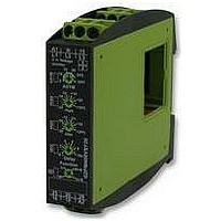
RELAY, VOLTAGE MONITORING, 3-PHASE
Manufacturer
TELE
Series
GAMMAr
Datasheet
1.G2PM400VSY20.pdf
(3 pages)
Specifications of G2PM400VSY20
Contact Configuration
DPCO
Power Consumption
1W
Supply Voltage Max
240V
Relay Mounting
DIN Rail
Svhc
No SVHC (18-Jun-2010)
Contact Current Ac Max
5A
Contact Voltage Ac Max
250V
Lead Free Status / RoHS Status
Lead free / RoHS Compliant


Functions
For all the functions the LEDs MIN and MAX are flashing alternating,
when the minimum value for the measured voltage was chosen to be
greater than the maximum value. If a failure already exists when the
device is activated, the output relays remain in off-position and the LED
for the corresponding threshold is illuminated.
Under voltage monitoring (UNDER, UNDER+SEQ)
When the measured voltage (mean value of phase-to-phase voltages)
falls below the value adjusted at the MIN-regulator, the set interval of the
tripping delay (DELAY) begins (red LED MIN flashes). After the interval
has expired (red LED MIN illuminated), the output relays switch into
off-position (yellow LED not illuminated). The output relays again switch
into on-position (yellow LED illuminated), when the measured voltage
exceeds the value adjusted at the MAX-regulator.
Window function (WIN, WIN+SEQ)
The output relays switch into on-position (yellow LED illuminated) when
the measured voltage (mean value of phase-to-phase voltages) exceeds
the value adjusted at the MIN-regulator. When the measured voltage
exceeds the value adjusted at the MAX-regulator, the set interval of the
tripping delay (DELAY) begins (red LED MAX flashes). After the interval
has expired (red LED MAX illuminated), the output relays switch into
off-position (yellow LED not illuminated). The output relays again switch
into on-position (yellow LED illuminated) when the measured voltage
falls below the value adjusted at the MAX-regulator (red LED MAX not
illuminated). When the measured voltage falls below the value adjusted
at the MIN-regulator, the set interval of the tripping delay (DELAY)
begins again (red LED MIN flashes). After the interval has expired (red
LED MIN illuminated), the output relays switch into off-position (yellow
LED not illuminated).
Phase sequence monitoring (SEQ)
Phase sequence monitoring is selectable for all functions.
If a change in phase sequence is detected (red LED SEQ illuminated),
the output relays switch into off-position immediately (yellow LED not
illuminated).
LED SEQ
L1
L2
L3
www.tele-online.com
Phase failure monitoring (SEQ)
If one of the phase voltages fails, the set interval of the tripping delay
(DELAY) begins (red LED SEQ flashes). After the interval has expired
(red LED SEQ illuminated), the output relays switch into off-position
(yellow LED not illuminated). Reverse voltages of a consumer (e.g.
a motor which continues to run on two phases only) do not effect the
disconnection but can be monitored by using a proper value for the
asymmetry.
Asymmetry monitoring
If the asymmetry of the phase-to-phase voltages exceeds the value set
at the ASYM-regulator, the set interval of the tripping delay (DELAY)
begins (red LED ASYM flashes). After the interval has expired (red LED
ASYM illuminated), the output relays switch into off-position (yellow
LED not illuminated). If the neutral wire is connected to the device,
the asymmetry of the phase voltages referred to the neutral wire
(Y-voltage) is monitored also. In that case both values of the asymmetry
are evaluated and if one of the values exceeds the value set at the
ASYM-regulator, the set interval of the tripping delay (DELAY) begins
(red LED ASYM flashes). After the interval has expired (red LED ASYM
illuminated), the output relays switch into off-position (yellow LED not
illuminated).
Loss of neutral wire by means of evaluation of asymmetry
A break of the neutral wire between power line and machinery is
detected as soon as asymmetry between phase-to-phase voltage and
neutral wire occurs. If the asymmetry exceeds the value set at the
ASYM-regulator, the set interval of the tripping delay (DELAY) begins
(red LED ASYM flashes). After the interval has expired (red LED ASYM
illuminated), the output relays switch into off-position (yellow LED not
illuminated). A break of the neutral wire between our device and the
machinery can not be detected.
LED ASYM
LED SEQ
Asym.
L1
L1
L2
L2
L3
L3
G2PM...SY20 24-240V
Delay
Delay
Related parts for G2PM400VSY20
Image
Part Number
Description
Manufacturer
Datasheet
Request
R

Part Number:
Description:
TELE DENSITY 39 DUAL
Manufacturer:
Tyco Electronics
Datasheet:

Part Number:
Description:
PUMP CONTROL, ALTERNATING/PARALLEL
Manufacturer:
TELE
Datasheet:

Part Number:
Description:
CURRENT MONITORING 1-PHASE
Manufacturer:
TELE
Datasheet:
Part Number:
Description:
VOLTAGE MONITORING 1 PHASE
Manufacturer:
TELE
Datasheet:

Part Number:
Description:
RELAY, VOLTAGE MONTR, 3-PHASE, 2 CO
Manufacturer:
TELE
Datasheet:

Part Number:
Description:
RELAY, VOLTAGE MONTR, MULTI FUN, 2 CO
Manufacturer:
TELE
Datasheet:

Part Number:
Description:
VOLTAGE LEVEL SWITCH, 0-10VDC
Manufacturer:
TELE
Datasheet:

Part Number:
Description:
RELAY, VOLTAGE PRESET, 0-10VDC
Manufacturer:
TELE
Datasheet:

Part Number:
Description:
ASYMMETRIC FLASHER, 1 CO
Manufacturer:
TELE
Datasheet:

Part Number:
Description:
STAR-DELTA TIMER, 2 NO
Manufacturer:
TELE
Datasheet: