Version 04/05
1. Function
One of two redundant motors will operate on demand
signalised by input Y1.
Successive requests will operate the motors in an alternating
sequence (sharing the duty between the devices).
On demand both devices (pumps) will operate in parallel:
Mode A (parallel operation by separate input signal):
Input Y2 initiates parallel operation. Without signal at input Y2,
only one single motor will operate at each request.
Mode B (parallel operation by timing):
If an operation request on input Y1 exceeds the ajdusted delay,
the unit will start the second motor for parallel operation.
2. Time ranges
t1 (for parallel operation)
t2 (offset timing)
3. Indicators
Green LED U/t ON:
Green LED U/t flashing:
Red LED Failure:
Yellow LED Rel. 1 ON/OFF:
Yellow LED Rel. 2 ON/OFF:
4. Mechanical design
Self -extinguishing plastic housing, IP rating IP 40
Mounted on DIN-rail TS 35 according to EN 50022
Mounting position :
Shockproof terminal connection according to VBG 4 (PZ1 required)
IP rating IP20
Tightening torque:
Terminal capacity:
5. Input circuit
Supply voltage:
Tolerance:
Rated frequency:
Rated consumption:
Duty cycle:
Reset time:
Residual ripple for DC:
Drop out voltage:
Overvoltage category:
Rated surge voltage:
Alternated access of two pumps or other devices
Even distribution of duty
Parallel duty at high demand
Operation using 1 or 2 input signals (two modes of operation)
Timing offset of the two loads to avoid water hammer effcects
Supply voltage selectable via TR2 power modules
2 separate change over relays for device control
Width 22.5mm
Industrial design
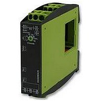
Pump-Alternator - GAMMA series
Technical data
1 x 0.5 bis 2.5mm2 with/without multicore cable end
1 x 4mm2 without multicore cable end
2 x 0.5 bis 1.5mm2 with/without multicore cable end
2 x 2.5mm2 flexible without multicore cable end
12 to 400V AC
654
Adjusment range
2s
2s fixed
indication of supply voltage
indication of time periode t1 or t2
irregular input; Y2 is activ while Y1 is off
indication of relay output Rel. 1
indication of relay output Rel. 2
any
terminals A1-A2 (galvanically separated)
selectable by powermodule typeTR2
according to specification of power module
according to specification of power module
2VA (1.5W)
100%
500ms
-
> 30% of nominal supply voltage
III (according to IEC 60444-1)
4kV
1 Nm max.
5min (use for mode B only)
6. Output circuit
2 potential free change over contacts
Rated voltage:
Switching capacity (distance <5mm):
Switching capacity (distance >5mm):
Fusing:
Mechanical life:
Electrical life
Switching frequency:
Over-voltage category:
rated surge voltage:
7. Control inputs
Y1 operation request:
Y2 parallel operation:
Potential free:
Loadable:
Control voltage:
Schort circuit current:
Wiring length:
Coltrol pulse length :
8. Accuracy
Adjustment accuracy (t1):
Repetition accuracy:
9. Ambient conditions
Ambient temperature:
Storage temperature:
Transport temperature:
Relative humidity:
Pollution degree:
Vibration resistance:
Shock resistance:
G2ASMA20
250V AC
750VA (3A / 250V)
1250VA (5A / 250V)
5A fast acting
20x10
2x10
at 1000VA resistive load
max. 60/min at 100VA at resistive load
max. 6/min at 1000VA at resistive load
according to IEC 947-5-1)
III (according to IEC 60664-1)
4kV
activation by link Y1-Y3
activation by link Y2-Y3 (mode A only)
yes, seperated from supply input
and output circuit by basic insulation
no
10V max.
1mA max.
10m max.
50ms min.
±5s
±30s in the Range above 30s
<5% of set value
-25 to +55° C (according to IEC 68-1)
-25 to +70° C
-25 to +70° C
15% to 85%
(according to IEC 721-3-3 Klasse 3k3)
3 (according to IEC 60664-1)
10 to 55 Hz 0.35mm
(according to IEC 68-2-6)
15g 11ms
5
6
in the Range up to 30s
operations
operations
(according to IEC 68-2-27)
E1ZM