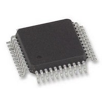
FM6124-QG Ramtron, FM6124-QG Datasheet - Page 14

FM6124-QG
Manufacturer Part Number
FM6124-QG
Description
FRAM, 24KB, EVENT DATA REC, QFP44
Manufacturer
Ramtron
Datasheet
1.FM6124-QG.pdf
(53 pages)
Specifications of FM6124-QG
Memory Size
24KB
Nvram Features
RTC
Supply Voltage Range
3V To 3.6V
Memory Case Style
QFP
No. Of Pins
44
Operating Temperature Range
-40°C To +85°C
Package / Case
QFP
Interface
I2C
Memory
RoHS Compliant
Interface Type
I2C, Serial, 2-Wire
Rohs Compliant
Yes
Access Time
100 KBPs
Operating Supply Voltage
3 V to 3.6 V
Mounting Style
SMD/SMT
Lead Free Status / Rohs Status
Details
Available stocks
Company
Part Number
Manufacturer
Quantity
Price
Company:
Part Number:
FM6124-QG
Manufacturer:
ABOV
Quantity:
3 000
Retrieving the Number of Unread Events
The FM6124 features a 16-bit register that indicate the
number of unread event present in the Event Buffer
memory. This 16-bit number actually corresponds to the
number of events between WP and RP pointers. It is
accessible through I
Before accessing the Unread Event counter, the host
processor must latch a internal registers content into the
16-bit register.
This is performed by writing 0x02 into the Pin/Event
Snapshot register.
Event buffer initial condition
Every time the FM6124 Event Buffer memory size
configuration is changed, by Event Buffer Memory will be
reinitialized the events records that may still be present
into the F-RAM will be erased.
process takes ~100µs and during that time no events will
be recorded and I
After initialization, the RP, WP, and FP pointers will all be
pointing at the base memory address as shown in the
diagram below.
The following example demonstrates the state of the
pointers after 3 events have been captured and stored in F-
RAM based Event buffer; the pointers will be positioned
as shown in the figure below:
Rev. 4.0 (EOL)
July 2010
F
IGURE
15. I
NITIAL CONDITION OF
2
2
C communication should be stopped.
C registers addresses 0x2A and 0x2B.
This re-initialization
E
VENT
B
UFFER
The FP, WP, and RP pointers will be set as follow:
Each time a new Event is recorded the WP address is
incremented. When WP increments beyond the Nmax
position, it will roll-over to FP and so on. If FP reached
WP, an error condition will occur.
As mentioned earlier, after a number of events have been
recorded and a number of events have been read, the RP
pointer will be away from FP and the WP pointer. In that
situation the Event data recorder makes possible to retrieve
either newer or older events by configuring the DIR bit
accordingly. The following diagram illustrates the impact
on the DIR register on the RP operation.
•
•
•
F
IGURE
WP will point to the next free position
RP point to the next Event to be read
FP is fix
F
IGURE
16. I
NTERNAL POINTERS AFTER
17. RP P
OINTER
D
IRECTION
Page 14 of 53
3
EVENTS


