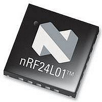
NRF24L01G NORDIC SEMICONDUCTOR, NRF24L01G Datasheet - Page 27

NRF24L01G
Manufacturer Part Number
NRF24L01G
Description
IC, RF TRANSCEIVER, 2.4-2.4835GHZ QFN-20
Manufacturer
NORDIC SEMICONDUCTOR
Datasheet
1.NRF24L01G.pdf
(74 pages)
Specifications of NRF24L01G
Transmitting Current
11.3mA
Data Rate
2Mbps
Frequency Range
2.4GHz To 2.4835GHz
Modulation Type
GFSK
Sensitivity Dbm
-82dBm
Rf Ic Case Style
QFN
No. Of Pins
20
Sensitivity (dbm)
-82dBm
Supply Voltage Range
1.9V To 3.6V
Rohs Compliant
Yes
Lead Free Status / RoHS Status
Lead free / RoHS Compliant
nRF24L01 Product Specification
With DPL feature the nRF24L01 can decode the payload length of the received packet automatically
instead of using the RX_PW_Px registers. The MCU can read the length of the received payload by using
the R_RX_PL_WID command.
In order to enable DPL the EN_DPL bit in the FEATURE register must be set. In RX mode the DYNPD reg-
ister has to be set. A PTX that transmits to a PRX with DPL enabled must have the DPL_P0 bit in DYNPD
set.
7.4.2
The automatic packet assembly assembles the preamble, address, packet control field, payload and CRC
to make a complete packet before it is transmitted.
7.4.2.1
The preamble is automaticly generated based on the address field.
7.4.2.2
The address is fetched from the TX_ADDR register. The address field can be configured to be 3, 4 or 5
bytes long with the AW register.
7.4.2.3
For the static packet lenght option the payload length field is not used. With DPL enabled, the value in the
payload length field is automaticly set to the number of bytes in the payload clocked into the TX FIFO.
The transmitter increments the PID field each time it generates a new packet and uses the same PID on
packets that are retransmitted. Refer to the left flow chart in
The PTX can set the NO_ACK flag bit in the Packet Control Field with this command:
W_TX_PAYLOAD_NOACK
However, the function must first be enabled in the FEATURE register by setting the EN_DYN_ACK bit.
When you use this option the PTX goes directly to standby-I mode after transmitting the packet and the
PRX does not transmit an ACK packet when it receives the packet.
7.4.2.4
The payload is fetched from the TX FIFO.
7.4.2.5
The CRC is automaticly calculated based on the packet content with the polynomials in
The number of bytes in the CRC is set by the CRCO bit in the CONFIG register.
7.4.3
Enhanced ShockBurst™ features automatic packet validation. In receive mode the nRF24L01 is constanly
searching for a valid address (given in the RX_ADDR registers.) If a valid address is detected the
Enhanched ShockBurst™ will start to validate the packet.
Revision 2.0
Automatic packet assembly
Automatic packet validation
Preamble
Address
Packet control field
Payload
CRC
Page 27 of 74
Figure 6. on page 28
7.3.5 on page
26.


