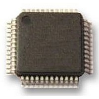
LPC2106FBD48/01 NXP Semiconductors, LPC2106FBD48/01 Datasheet - Page 19

LPC2106FBD48/01
Manufacturer Part Number
LPC2106FBD48/01
Description
IC, MCU, 32BIT, 128K FLASH, 48LQFP
Manufacturer
NXP Semiconductors
Datasheet
1.LPC2105FBD48.pdf
(41 pages)
Specifications of LPC2106FBD48/01
Controller Family/series
ARM7
No. Of I/o's
32
Ram Memory Size
64KB
Cpu Speed
60MHz
No. Of Timers
3
No. Of Pwm
RoHS Compliant
Core Size
32bit
Program Memory Size
128KB
Oscillator Type
Internal, External
Available stocks
Company
Part Number
Manufacturer
Quantity
Price
Company:
Part Number:
LPC2106FBD48/01
Manufacturer:
NXP
Quantity:
670
Company:
Part Number:
LPC2106FBD48/01
Manufacturer:
NXP
Quantity:
7 750
Company:
Part Number:
LPC2106FBD48/01,15
Manufacturer:
NXP
Quantity:
250
Company:
Part Number:
LPC2106FBD48/01,15
Manufacturer:
NXP Semiconductors
Quantity:
10 000
NXP Semiconductors
LPC2104_2105_2106_7
Product data sheet
6.14.1 Features
6.14.2 Features available in LPC2104/2105/2106/01 only
6.15.1 Features
6.15 Watchdog timer
The LPC2104/2105/2106/01 can count external events on one of the capture inputs if the
external pulse lasts at least one half of the period of the PCLK. In this configuration,
unused capture lines can be selected as regular timer capture inputs or used as external
interrupts.
The purpose of the Watchdog is to reset the microcontroller within a reasonable amount of
time if it enters an erroneous state. When enabled, the Watchdog will generate a system
reset if the user program fails to ‘feed’ (or reload) the Watchdog within a predetermined
amount of time.
•
•
•
•
•
•
•
•
•
•
•
A 32-bit Timer/Counter with a programmable 32-bit Prescaler.
Up to four (Timer 1) and three (Timer 0) 32-bit capture channels, that can take a
snapshot of the timer value when an input signal transitions. A capture event may also
optionally generate an interrupt.
Four 32-bit match registers that allow:
– Continuous operation with optional interrupt generation on match.
– Stop timer on match with optional interrupt generation.
– Reset timer on match with optional interrupt generation.
Up to four (Timer 1) and three (Timer 0) external outputs corresponding to match
registers, with the following capabilities:
– Set LOW on match.
– Set HIGH on match.
– Toggle on match.
– Do nothing on match.
Timer can count cycles of either the peripheral clock (PCLK) or an externally supplied
clock.
When counting cycles of an externally supplied clock, only one of the timer’s capture
inputs can be selected as the timer’s clock. The rate of such a clock is limited to
PCLK
than
Internally resets chip if not periodically reloaded.
Debug mode.
Enabled by software but requires a hardware reset or a watchdog reset/interrupt to be
disabled.
Incorrect/Incomplete feed sequence causes reset/interrupt if enabled.
Flag to indicate watchdog reset.
4
1
. Duration of HIGH/LOW levels on the selected CAP input cannot be shorter
(2PCLK)
.
Rev. 07 — 20 June 2008
LPC2104/2105/2106
Single-chip 32-bit microcontrollers
© NXP B.V. 2008. All rights reserved.
19 of 41


