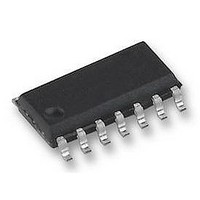
FM31274-G Ramtron, FM31274-G Datasheet - Page 15

FM31274-G
Manufacturer Part Number
FM31274-G
Description
FRAM, MPU SUPPORT, 16K, RTC, SOIC14
Manufacturer
Ramtron
Datasheet
1.FM31274-G.pdf
(26 pages)
Specifications of FM31274-G
Memory Size
16Kbit
Nvram Features
RTC
Supply Voltage Range
4V To 5.5V
Memory Case Style
SOIC
No. Of Pins
14
Operating Temperature Range
-40°C To +85°C
Interface
Serial
Package / Case
SOIC
Memory Configuration
2048 X 8
Interface Type
I2C, Serial, 2-Wire
Rohs Compliant
Yes
Lead Free Status / RoHS Status
Lead free / RoHS Compliant
Available stocks
Company
Part Number
Manufacturer
Quantity
Price
Company:
Part Number:
FM31274-GTR
Manufacturer:
CYPRESS
Quantity:
2 500
Part Number:
FM31274-GTR
Manufacturer:
RAMTRON
Quantity:
20 000
Rev. 2.0
Jan. 2011
01h
/OSCEN
Reserved
CALS
CAL.4-0
00h
CF
CAL
W
R
Reserved
CAL/Control
/Oscillator Enable. When set to 1, the oscillator is halted. When set to 0, the oscillator runs. Disabling the
oscillator can save battery power during storage. On a power-up without battery, this bit is set to 1. Battery-
backed, read/write.
Reserved bits. Do not use. Should remain set to 0.
Calibration sign. Determines if the calibration adjustment is applied as an addition to or as a subtraction from
the time-base. Calibration is explained on page 7. Nonvolatile, read/write.
These five bits control the calibration of the clock. Nonvolatile, read/write.
Flags/Control
Century Overflow Flag. This bit is set to a 1 when the values in the years register overflows from 99 to 00. This
indicates a new century, such as going from 1999 to 2000 or 2099 to 2100. The user should record the new
century information as needed. This bit is cleared to 0 when the Flag register is read. It is read-only for the user.
Battery-backed.
Calibration Mode. When set to 1, the clock enters calibration mode. When CAL is set to 0, the clock operates
normally, and the CAL/PFO pin is controlled by the power fail comparator. Battery-backed, read/write.
Write Time. Setting the W bit to 1 freezes the clock. The user can then write the timekeeping registers with
updated values. Resetting the W bit to 0 causes the contents of the time registers to be transferred to the
timekeeping counters and restarts the clock. Battery-backed, read/write.
Read Time. Setting the R bit to 1 copies a static image of the timekeeping core and place it into the user
registers. The user can then read them without concerns over changing values causing system errors. The R bit
going from 0 to 1 causes the timekeeping capture, so the bit must be returned to 0 prior to reading again.
Battery-backed, read/write.
Reserved bits. Do not use. Should remain set to 0.
Reserved
OSCEN
D7
D7
Reserved
D6
D6
CF
Reserved
CALS
D5
D5
Reserved
CAL.4
D4
D4
FM31L278/L276/L274/L272 - 3V I2C Companion
Reserved
CAL.3
D3
D3
CAL.2
CAL
D2
D2
CAL.1
D1
D1
W
Page 15 of 26
CAL.0
D0
D0
R


